VOGONS


First post, by biessea

User metadata
Rank Member
Rank
Member

Hi there,

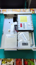
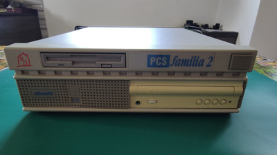
Yesterday I finally acquired this nice old system, I just bought it near my home, at about one hour of train.

The seller was kind and explained me that the computer can boot, pass regularly the memory test and the other testa, when error 8 came at the relevation of keyboard.

So when I took to my home I found that big mistere.

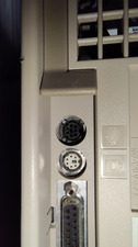
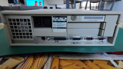
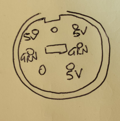
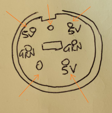
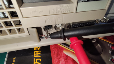
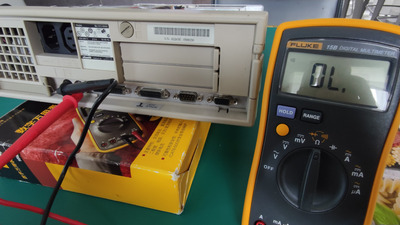
The keyboard connector was somewhat different from a ps/2 connector like the mouse one is.

I put some photos here so you all can see and I really hope that the mistery could be solved cause at the moment I cannot go deeper on the boot procedure.

I have already check at home but I have no clue and never seen a connector like this one.

I have some ps/2 keyboard, Olivetti too... And some DIN older keyboard.

Please I really hope someone can help and follow me in this tragedy of connection!

Attachments

  • IMG_20230427_165549.jpg
    Filename
    IMG_20230427_165549.jpg
    File size
    1.12 MiB
    Views
    1234 views
    File comment
    Strange connector
    File license
    Public domain
  • IMG_20230427_161427.jpg
    Filename
    IMG_20230427_161427.jpg
    File size
    1.2 MiB
    Views
    1234 views
    File comment
    Inside the Olivetti Familia 2 PCS
    File license
    Public domain
  • IMG_20230427_161130.jpg
    Filename
    IMG_20230427_161130.jpg
    File size
    1.22 MiB
    Views
    1234 views
    File comment
    Back of the Olivetti Familia 2 PCS
    File license
    Public domain
  • IMG_20230427_161116.jpg
    Filename
    IMG_20230427_161116.jpg
    File size
    1.05 MiB
    Views
    1234 views
    File comment
    Front of the Olivetti Familia 2 PCS
    File license
    Public domain

Computer lover since 1992.
Love retro-computing, retro-gaming, high-end systems and all about computer-tech.
Love beer, too.

Reply 2 of 90, by biessea

User metadata
Rank Member
Rank
Member
Doornkaat wrote on 2023-04-28, 14:46:

The connector is a regular 7 pin mini DIN.
Don't know the pinout.🤷‍♂️
https://commons.m.wikimedia.org/wiki/File:Sta … _and_female.jpg

Thanks, and that is a begin. Someone know why I found that connector in this system instead of a ps/2?

There is some ps/2 to 7 pin mini DIN converter?

Computer lover since 1992.
Love retro-computing, retro-gaming, high-end systems and all about computer-tech.
Love beer, too.

Reply 5 of 90, by biessea

User metadata
Rank Member
Rank
Member
Doornkaat wrote on 2023-04-28, 15:20:

I found pictures of another BU 313-XXXX. It has a normal 6pin mini DIN PS/2 connector.
Maybe somebody modded this motherboard?

I really don't know about that, but trust me, I was thinking the same.

It's like something isn't going right with this computer.

As I read more about that 7 pin mini din connector I see that it wasn't never used for keyboard.

But why do this?

I have no explaination.

It is a good though to desolder this connector and solder a normal ps/2 connector like I saw in another Olivetti PCS familia 2?

Computer lover since 1992.
Love retro-computing, retro-gaming, high-end systems and all about computer-tech.
Love beer, too.

Reply 6 of 90, by biessea

User metadata
Rank Member
Rank
Member
Doornkaat wrote on 2023-04-28, 15:15:

You could try tracing the pins' signals on the mainboard. Maybe it's only using four pins like the regular PS/2 and you can build an adaptor yourself.

I really don't know how to do it.

If I knew I did without doubt.

Computer lover since 1992.
Love retro-computing, retro-gaming, high-end systems and all about computer-tech.
Love beer, too.

Reply 7 of 90, by Doornkaat

User metadata
Rank l33t
Rank
l33t

I can't tell you if you can just replace the connector with a 6 pin one. I'd need need to be able to trace the connections for that.

Can you get the board out of the case and post pics of the area of the connectors?

Also do you have a basic multimeter?

Reply 8 of 90, by paradigital

User metadata
Rank Oldbie
Rank
Oldbie

My guess is that it was used for something financial or EPOS like. And the keyboard was possibly custom for that environment.

My father worked for Olivetti during the 80s and 90s and we had no end of weird and wonderful devices in the garage that had come home from work. Keyboards with magstripe readers and passbook readers were a common sight, though I was far too young at the time to go checking if the machines all had standard PS/2 connectors or not.

As his role was customer facing, he’d be demoing for large banks and building societies all the time.

Reply 9 of 90, by biessea

User metadata
Rank Member
Rank
Member
Doornkaat wrote on 2023-04-28, 16:04:

I can't tell you if you can just replace the connector with a 6 pin one. I'd need need to be able to trace the connections for that.

Can you get the board out of the case and post pics of the area of the connectors?

Also do you have a basic multimeter?

Yes, I can. I will extract the motherboard from the case and put some photos.

Yes, I have a Fluke Multimeter.

I am on holiday now but on Wednesday I will return home!

Computer lover since 1992.
Love retro-computing, retro-gaming, high-end systems and all about computer-tech.
Love beer, too.

Reply 10 of 90, by biessea

User metadata
Rank Member
Rank
Member
paradigital wrote on 2023-04-28, 16:23:

My guess is that it was used for something financial or EPOS like. And the keyboard was possibly custom for that environment.

My father worked for Olivetti during the 80s and 90s and we had no end of weird and wonderful devices in the garage that had come home from work. Keyboards with magstripe readers and passbook readers were a common sight, though I was far too young at the time to go checking if the machines all had standard PS/2 connectors or not.

As his role was customer facing, he’d be demoing for large banks and building societies all the time.

Thanks for the experience.
Probably it was used for other purposes! But I think I will need to replace the connector!

Computer lover since 1992.
Love retro-computing, retro-gaming, high-end systems and all about computer-tech.
Love beer, too.

Reply 11 of 90, by Doornkaat

User metadata
Rank l33t
Rank
l33t
biessea wrote on 2023-04-28, 23:07:
Yes, I can. I will extract the motherboard from the case and put some photos. […]
Show full quote
Doornkaat wrote on 2023-04-28, 16:04:

I can't tell you if you can just replace the connector with a 6 pin one. I'd need need to be able to trace the connections for that.

Can you get the board out of the case and post pics of the area of the connectors?

Also do you have a basic multimeter?

Yes, I can. I will extract the motherboard from the case and put some photos.

Yes, I have a Fluke Multimeter.

I am on holiday now but on Wednesday I will return home!

Great!👍 Enjoy your holiday!😃

Reply 12 of 90, by bogdanpaulb

User metadata
Rank Member
Rank
Member

There is no need for disassembly of the hole computer: you only need a multimeter and a needle .

1 : use the screw nut as gnd for the one lead of the multimeter (diode/beep/continuity mode) and the needle for the second lead to probe the holes of the din connector to isolate ground. Save it on the pin layout.(computer off)

2: use the screw nut as gnd for the one lead of the multimeter (voltage mode) and the needle for the second lead to probe the holes of the din connector to isolate 5v dc. Save it on the pin layout.(computer on)

3: use the screw nut as gnd for the red lead of the multimeter (diode/beep/continuity mode) and the needle for the black lead to probe the rest of holes of the din connector to isolate clk and data pins, depending of the internal circuitry you should have a value of ~700 (multimeter in diode/beep/continuity mode) when the red probe is connected to the ground and the black one is connected to the signal pin. Save those 2 pins on the pin layout with a question mark.(computer off)

All you need now is to find out which of the 2 pins is clk and which is data. You can find out by using a scope or connecting the data and clk wires from a powered (trough ground and 5v pins that you already found) keyboard and and see which way it works (reverse them if necessary). No motherboard/keyboard should be able to get destroyed by only reversing the clk and data pins between them, just be careful not to short/touch them on something else.

Attachments

  • keyb.jpg
    Filename
    keyb.jpg
    File size
    1.25 MiB
    Views
    1093 views
    File license
    Fair use/fair dealing exception

Reply 13 of 90, by biessea

User metadata
Rank Member
Rank
Member
bogdanpaulb wrote on 2023-04-29, 16:13:
There is no need for disassembly of the hole computer: you only need a multimeter and a needle . […]
Show full quote

There is no need for disassembly of the hole computer: you only need a multimeter and a needle .

1 : use the screw nut as gnd for the one lead of the multimeter (diode/beep/continuity mode) and the needle for the second lead to probe the holes of the din connector to isolate ground. Save it on the pin layout.(computer off)

2: use the screw nut as gnd for the one lead of the multimeter (voltage mode) and the needle for the second lead to probe the holes of the din connector to isolate 5v dc. Save it on the pin layout.(computer on)

3: use the screw nut as gnd for the red lead of the multimeter (diode/beep/continuity mode) and the needle for the black lead to probe the rest of holes of the din connector to isolate clk and data pins, depending of the internal circuitry you should have a value of ~700 (multimeter in diode/beep/continuity mode) when the red probe is connected to the ground and the black one is connected to the signal pin. Save those 2 pins on the pin layout with a question mark.(computer off)

All you need now is to find out which of the 2 pins is clk and which is data. You can find out by using a scope or connecting the data and clk wires from a powered (trough ground and 5v pins that you already found) keyboard and and see which way it works (reverse them if necessary). No motherboard/keyboard should be able to get destroyed by only reversing the clk and data pins between them, just be careful not to short/touch them on something else.

Thanks for the hint.

I admit I am not so good in electronic, but I can use a multimeter, or I can desolder and solder component.

But I didn't know what do you mean when you say "use the screw nut as ground".
What's the screw nut?

And what's the "needle"?

ThenI think I can do that test on Wednesday as I return home from my holiday in Turin, Italy.

Computer lover since 1992.
Love retro-computing, retro-gaming, high-end systems and all about computer-tech.
Love beer, too.

Reply 14 of 90, by bogdanpaulb

User metadata
Rank Member
Rank
Member

https://en.wikipedia.org/wiki/Sewing_needle or any piece of metal that will fit the holes of the 'din' keyboard connector from your computer, because i think the leads of your multimeter wont fit.
https://www.jaycar.com.au/locking-nuts-for-co … -pairs/p/PM0852, you have it in the picture i posted selected with orange.

Reply 15 of 90, by biessea

User metadata
Rank Member
Rank
Member
bogdanpaulb wrote on 2023-04-29, 23:29:

https://en.wikipedia.org/wiki/Sewing_needle or any piece of metal that will fit the holes of the 'din' keyboard connector from your computer, because i think the leads of your multimeter wont fit.
https://www.jaycar.com.au/locking-nuts-for-co … -pairs/p/PM0852, you have it in the picture i posted selected with orange.

Ok Bogdan, I understood all.

Then on Wednesday when I will return home from my Holiday I will do what you ask me.

Thanks for the help, I will immediately let you know

Loris

Computer lover since 1992.
Love retro-computing, retro-gaming, high-end systems and all about computer-tech.
Love beer, too.

Reply 16 of 90, by biessea

User metadata
Rank Member
Rank
Member
bogdanpaulb wrote on 2023-04-29, 16:13:
There is no need for disassembly of the hole computer: you only need a multimeter and a needle . […]
Show full quote

There is no need for disassembly of the hole computer: you only need a multimeter and a needle .

1 : use the screw nut as gnd for the one lead of the multimeter (diode/beep/continuity mode) and the needle for the second lead to probe the holes of the din connector to isolate ground. Save it on the pin layout.(computer off)

2: use the screw nut as gnd for the one lead of the multimeter (voltage mode) and the needle for the second lead to probe the holes of the din connector to isolate 5v dc. Save it on the pin layout.(computer on)

3: use the screw nut as gnd for the red lead of the multimeter (diode/beep/continuity mode) and the needle for the black lead to probe the rest of holes of the din connector to isolate clk and data pins, depending of the internal circuitry you should have a value of ~700 (multimeter in diode/beep/continuity mode) when the red probe is connected to the ground and the black one is connected to the signal pin. Save those 2 pins on the pin layout with a question mark.(computer off)

All you need now is to find out which of the 2 pins is clk and which is data. You can find out by using a scope or connecting the data and clk wires from a powered (trough ground and 5v pins that you already found) keyboard and and see which way it works (reverse them if necessary). No motherboard/keyboard should be able to get destroyed by only reversing the clk and data pins between them, just be careful not to short/touch them on something else.

Here I am Bogdan.

I made the test you ask me, and first two point was successful for me to find GRND (two pins) and the 5v pins (three pins).
I put the picture about the results.
Then, the three point you asked me to test, I don't know but I had no success, cause I always result woth a 0 for me. No ~700 rilevation.
What to do now?
Anyway I am not sure to have understand what O have to do to find the DATA and the CLK pin now.
How I connect a Keyboard if the connector is different and it doesn't fit??

Attachments

  • IMG_20230503_095811.jpg
    Filename
    IMG_20230503_095811.jpg
    File size
    217.16 KiB
    Views
    989 views
    File comment
    Standard 7 pin mini din pinout
    File license
    Public domain

Computer lover since 1992.
Love retro-computing, retro-gaming, high-end systems and all about computer-tech.
Love beer, too.

Reply 17 of 90, by dionb

User metadata
Rank l33t++
Rank
l33t++
biessea wrote on 2023-05-03, 08:01:

[...]

How I connect a Keyboard if the connector is different and it doesn't fit??

Best solution: get a connector that does fit, then connect your connector to that.

Temporary solution to figure out pinout: use four or five needles and connect via them.

Connect +5V and GND for power, then play around with the other pins.

It's possible if you are measuring +5V on three pins only one is actually the Vcc power line and the other two are data. With an oscilloscope or logic analyzer you could figure that out very quickly; without one, you can use a little 5V lightbulb: the 'real' +5V line will have a 100% duty cycle, so will make the light shine at full strenght. A data line will have a lower duty cycle, so will make the light shine less brightly, or not at all.

Reply 18 of 90, by bogdanpaulb

User metadata
Rank Member
Rank
Member
biessea wrote on 2023-05-03, 08:01:
Here I am Bogdan. […]
Show full quote
bogdanpaulb wrote on 2023-04-29, 16:13:
There is no need for disassembly of the hole computer: you only need a multimeter and a needle . […]
Show full quote

There is no need for disassembly of the hole computer: you only need a multimeter and a needle .

1 : use the screw nut as gnd for the one lead of the multimeter (diode/beep/continuity mode) and the needle for the second lead to probe the holes of the din connector to isolate ground. Save it on the pin layout.(computer off)

2: use the screw nut as gnd for the one lead of the multimeter (voltage mode) and the needle for the second lead to probe the holes of the din connector to isolate 5v dc. Save it on the pin layout.(computer on)

3: use the screw nut as gnd for the red lead of the multimeter (diode/beep/continuity mode) and the needle for the black lead to probe the rest of holes of the din connector to isolate clk and data pins, depending of the internal circuitry you should have a value of ~700 (multimeter in diode/beep/continuity mode) when the red probe is connected to the ground and the black one is connected to the signal pin. Save those 2 pins on the pin layout with a question mark.(computer off)

All you need now is to find out which of the 2 pins is clk and which is data. You can find out by using a scope or connecting the data and clk wires from a powered (trough ground and 5v pins that you already found) keyboard and and see which way it works (reverse them if necessary). No motherboard/keyboard should be able to get destroyed by only reversing the clk and data pins between them, just be careful not to short/touch them on something else.

Here I am Bogdan.

I made the test you ask me, and first two point was successful for me to find GRND (two pins) and the 5v pins (three pins).
I put the picture about the results.
Then, the three point you asked me to test, I don't know but I had no success, cause I always result woth a 0 for me. No ~700 rilevation.
What to do now?
Anyway I am not sure to have understand what O have to do to find the DATA and the CLK pin now.
How I connect a Keyboard if the connector is different and it doesn't fit??

Ok, now i need you to :
with the computer off/unplugged from mains, use the screw nut as gnd for the red lead of the multimeter (diode/beep/continuity mode) and the needle for the black lead to probe the rest of holes of the din connector to isolate clk and data pins, depending of the internal circuitry you should have a value of ~700 (multimeter in diode/beep/continuity mode) when the red probe is connected to the ground and the black one is connected to the signal pin and give me the values for the selected pins. The data lines (clock and data) will be the same, actual 5vdc will be different.

Attachments

  • partial.jpg
    Filename
    partial.jpg
    File size
    232.54 KiB
    Views
    967 views
    File license
    Fair use/fair dealing exception

Reply 19 of 90, by biessea

User metadata
Rank Member
Rank
Member
bogdanpaulb wrote on 2023-05-03, 09:54:
biessea wrote on 2023-05-03, 08:01:
Here I am Bogdan. […]
Show full quote
bogdanpaulb wrote on 2023-04-29, 16:13:
There is no need for disassembly of the hole computer: you only need a multimeter and a needle . […]
Show full quote

There is no need for disassembly of the hole computer: you only need a multimeter and a needle .

1 : use the screw nut as gnd for the one lead of the multimeter (diode/beep/continuity mode) and the needle for the second lead to probe the holes of the din connector to isolate ground. Save it on the pin layout.(computer off)

2: use the screw nut as gnd for the one lead of the multimeter (voltage mode) and the needle for the second lead to probe the holes of the din connector to isolate 5v dc. Save it on the pin layout.(computer on)

3: use the screw nut as gnd for the red lead of the multimeter (diode/beep/continuity mode) and the needle for the black lead to probe the rest of holes of the din connector to isolate clk and data pins, depending of the internal circuitry you should have a value of ~700 (multimeter in diode/beep/continuity mode) when the red probe is connected to the ground and the black one is connected to the signal pin. Save those 2 pins on the pin layout with a question mark.(computer off)

All you need now is to find out which of the 2 pins is clk and which is data. You can find out by using a scope or connecting the data and clk wires from a powered (trough ground and 5v pins that you already found) keyboard and and see which way it works (reverse them if necessary). No motherboard/keyboard should be able to get destroyed by only reversing the clk and data pins between them, just be careful not to short/touch them on something else.

Here I am Bogdan.

I made the test you ask me, and first two point was successful for me to find GRND (two pins) and the 5v pins (three pins).
I put the picture about the results.
Then, the three point you asked me to test, I don't know but I had no success, cause I always result woth a 0 for me. No ~700 rilevation.
What to do now?
Anyway I am not sure to have understand what O have to do to find the DATA and the CLK pin now.
How I connect a Keyboard if the connector is different and it doesn't fit??

Ok, now i need you to :
with the computer off/unplugged from mains, use the screw nut as gnd for the red lead of the multimeter (diode/beep/continuity mode) and the needle for the black lead to probe the rest of holes of the din connector to isolate clk and data pins, depending of the internal circuitry you should have a value of ~700 (multimeter in diode/beep/continuity mode) when the red probe is connected to the ground and the black one is connected to the signal pin and give me the values for the selected pins. The data lines (clock and data) will be the same, actual 5vdc will be different.

I am sorry Bogdan, but I didn't get any value.

I put photos so you can see how i measured all.

Attachments

  • IMG_20230503_123100.jpg
    Filename
    IMG_20230503_123100.jpg
    File size
    1.05 MiB
    Views
    957 views
    File comment
    Connections
    File license
    Public domain
  • IMG_20230503_123112.jpg
    Filename
    IMG_20230503_123112.jpg
    File size
    986.44 KiB
    Views
    957 views
    File comment
    No value for the multimeter
    File license
    Public domain

Computer lover since 1992.
Love retro-computing, retro-gaming, high-end systems and all about computer-tech.
Love beer, too.