Reply 20 of 90, by bogdanpaulb
Rank
Member
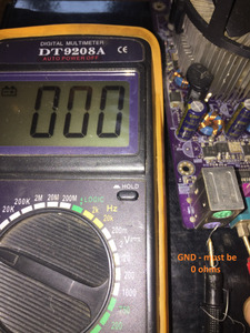
If you use the 'gnd' pins from the mini din connector, do you get any values? There should be some pins you wont get any reading, but not on all of them.
If you use the 'gnd' pins from the mini din connector, do you get any values? There should be some pins you wont get any reading, but not on all of them.
Only in the GND pin on the left I have a reading, 38 ohm.
Computer lover since 1992.
Love retro-computing, retro-gaming, high-end systems and all about computer-tech.
Love beer, too.
Try with another multimeter, preferably one that does not use auto scaling.
bogdanpaulb wrote on 2023-05-03, 14:42:Try with another multimeter, preferably one that does not use auto scaling.
I have only this one, is a Fluke.
Do you want me to fix a scale? I can do it
Computer lover since 1992.
Love retro-computing, retro-gaming, high-end systems and all about computer-tech.
Love beer, too.
dionb wrote on 2023-05-03, 08:33:Best solution: get a connector that does fit, then connect your connector to that. […]
biessea wrote on 2023-05-03, 08:01:[...]
How I connect a Keyboard if the connector is different and it doesn't fit??
Best solution: get a connector that does fit, then connect your connector to that.
Temporary solution to figure out pinout: use four or five needles and connect via them.
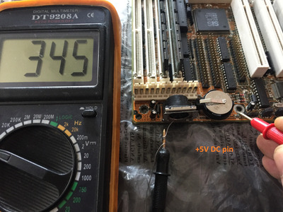
Connect +5V and GND for power, then play around with the other pins.
It's possible if you are measuring +5V on three pins only one is actually the Vcc power line and the other two are data. With an oscilloscope or logic analyzer you could figure that out very quickly; without one, you can use a little 5V lightbulb: the 'real' +5V line will have a 100% duty cycle, so will make the light shine at full strenght. A data line will have a lower duty cycle, so will make the light shine less brightly, or not at all.
Can you be more exaustive?
I didn't understand your explaination, I have to but a ps2 flying connector you are tell me?
Computer lover since 1992.
Love retro-computing, retro-gaming, high-end systems and all about computer-tech.
Love beer, too.
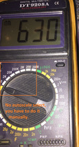
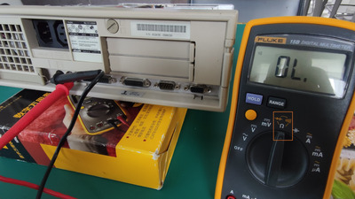
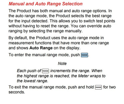
Without auto scale means, you have to select manually what you are measuring. I used this method many times and worked every time, here is another motherboard:
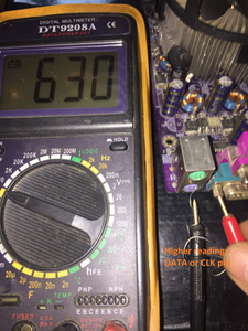
No auto scale:
Also the 38 ohms reading sounds off, either you are not making a good connection somewhere (e.g. in the hole of the mini din connector) or your multimeter has problems.
bogdanpaulb wrote on 2023-05-03, 15:19:No auto scale:
Also the 38 ohms reading sounds off, either you are not making a good connection somewhere (e.g. in the hole of the mini din connector) or your multimeter has problems.
I don't know what to say.
If it can help If I put the multimeter in measuring ohm I had some values with manual scale or auto scale.
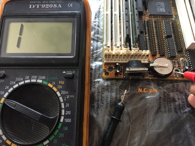
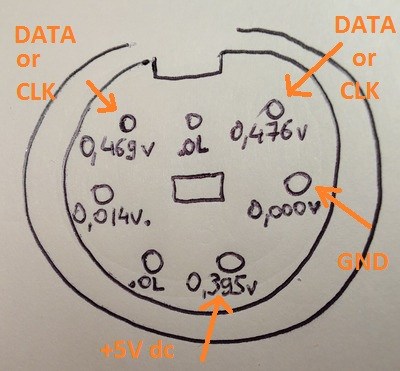
I put the photo about what I measured.
Red multimeter pin on Grnd and the black in the various holes.
Ps: putting the multimeter on continuity mode cannot make me select the scale, no manual no auto, probably because it's not meaning to misure something but only the continuity.
Please help me how to continue.
Computer lover since 1992.
Love retro-computing, retro-gaming, high-end systems and all about computer-tech.
Love beer, too.
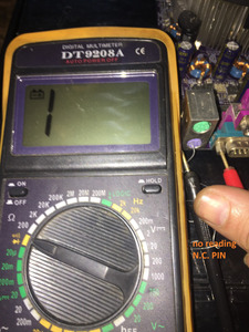
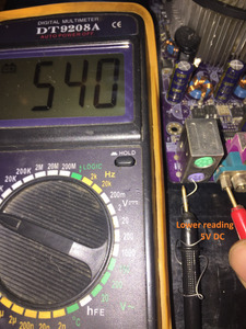
Again, your tool is using automode and this is not the best option for this measurement. Try to put it in manual mode( diode mode ) or borrow/get one that uses manual mode.
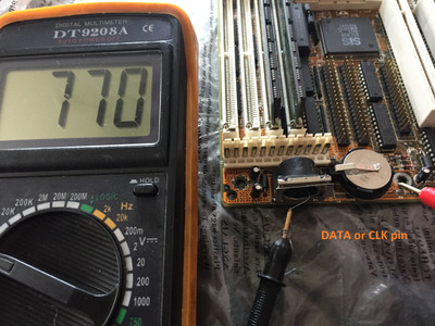
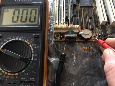
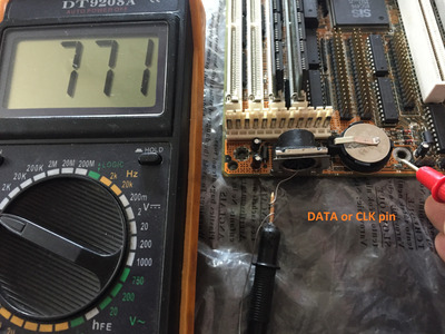
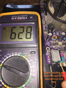
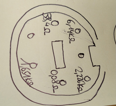
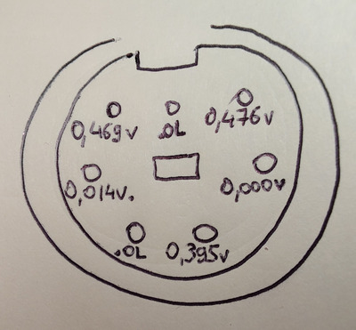
The results are quite clear, though. 0,08Ω to ground is GND. 38Ω to ground is Vcc. The other three pins that are not "open circuit" are data pins, two of them likely regular PS/2 clock and data, and the last one special purpose (XT compatible reset?)
If you overlay the 7-pin layout with the regular PS/2 6-pin layout, and call the extra pin "7", you will find that ground and Vcc on pins 3 and 4 are a perfect match. Also clk/data on 1 and 5 match two of the pins with kOhm reading. Pin 2 and the extra pin Pin 7 are not connected, but some special-purpose signal on pin 6 overlays an unused PS/2 pin.
It is likely that a keyboard with the plastic keying block removed from the Mini-DIN plug will fit and work fine. You better remove the key pin from an PS/2 extension cord than from an actual keyboard, though.
mkarcher wrote on 2023-05-03, 16:25:The results are quite clear, though. 0,08Ω to ground is GND. 38Ω to ground is Vcc. The other three pins that are not "open circuit" are data pins, two of them likely regular PS/2 clock and data, and the last one special purpose (XT compatible reset?)
If you overlay the 7-pin layout with the regular PS/2 6-pin layout, and call the extra pin "7", you will find that ground and Vcc on pins 3 and 4 are a perfect match. Also clk/data on 1 and 5 match two of the pins with kOhm reading. Pin 2 and the extra pin Pin 7 are not connected, but some special-purpose signal on pin 6 overlays an unused PS/2 pin.
It is likely that a keyboard with the plastic keying block removed from the Mini-DIN plug will fit and work fine. You better remove the key pin from an PS/2 extension cord than from an actual keyboard, though.
They don't match the measurements from the first page for 5v dc thou. So there is a mistake somewhere.
bogdanpaulb wrote on 2023-05-03, 16:01:Again, your tool is using automode and this is not the best option for this measurement. Try to put it in manual mode( diode mode ) or borrow/get one that uses manual mode.
Ehy thanks Bogdan, finally I had understood.
I changed the mesuration with diode mode and now I have results.
I put an image of what I measured then.
Tell me now what to do.
Thanks a lot mate.
Computer lover since 1992.
Love retro-computing, retro-gaming, high-end systems and all about computer-tech.
Love beer, too.
mkarcher wrote on 2023-05-03, 16:25:The results are quite clear, though. 0,08Ω to ground is GND. 38Ω to ground is Vcc. The other three pins that are not "open circuit" are data pins, two of them likely regular PS/2 clock and data, and the last one special purpose (XT compatible reset?)
If you overlay the 7-pin layout with the regular PS/2 6-pin layout, and call the extra pin "7", you will find that ground and Vcc on pins 3 and 4 are a perfect match. Also clk/data on 1 and 5 match two of the pins with kOhm reading. Pin 2 and the extra pin Pin 7 are not connected, but some special-purpose signal on pin 6 overlays an unused PS/2 pin.
It is likely that a keyboard with the plastic keying block removed from the Mini-DIN plug will fit and work fine. You better remove the key pin from an PS/2 extension cord than from an actual keyboard, though.
Hi my friend and welcome.
I'm not sure that I understood what I have to do.
I have to find a rare keyboard with this connector so, or can I find an adapter?
Or can i desolder this stupid 7 pin connector and put the normal ps2 6pin connector like I saw in other Olivetti Familia 2 PCS?
Computer lover since 1992.
Love retro-computing, retro-gaming, high-end systems and all about computer-tech.
Love beer, too.
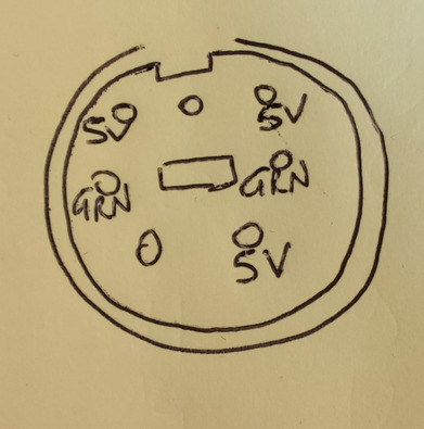
If the measurements from first page are correct (please make sure again), this should be the pinout.
I don't think you will find a keyboard with a matching plug. There are two ways to deal with it: Either you build an adapter cable, or you replace the socket.
To build an adapter cable, it very likely works if you take a standard PS/2 extension cable. That cable has 6 metal pins (or maybe just 4) that plug into the computer, as well as a plastic block to make sure you only insert this cable into the right type of socket (the 6-pin one), so it doesn't fit the 7-pin one. If you carefully remove that plastic pin/block, the standard PS/2 extension cable will also fit the 7-pin socket, and it will most likely work as adapter to connect a standard keyboard without modifying the computer.
Alternatively, you can replace the socket. Thi is only easy if a standard 6-pin sockets fits onto the mainboard. We can not know unless we see photos of the back side of the main board, where the 7-pin socket is soldered. Maybe looking at the board also gives a hint what the purpose of the extra pin might be.
bogdanpaulb wrote on 2023-05-03, 16:57:The if the measurements from first page are correct (please make sure again), this should be the pinout.
I can confirm the measurements.
What should I do now?
I ask me these testing to be sure the connector is working? Or the mainboard are ok?
Now what you suggest me to do?
Computer lover since 1992.
Love retro-computing, retro-gaming, high-end systems and all about computer-tech.
Love beer, too.
mkarcher wrote on 2023-05-03, 17:02:I don't think you will find a keyboard with a matching plug. There are two ways to deal with it: Either you build an adapter cable, or you replace the socket.
To build an adapter cable, it very likely works if you take a standard PS/2 extension cable. That cable has 6 metal pins (or maybe just 4) that plug into the computer, as well as a plastic block to make sure you only insert this cable into the right type of socket (the 6-pin one), so it doesn't fit the 7-pin one. If you carefully remove that plastic pin/block, the standard PS/2 extension cable will also fit the 7-pin socket, and it will most likely work as adapter to connect a standard keyboard without modifying the computer.
Alternatively, you can replace the socket. Thi is only easy if a standard 6-pin sockets fits onto the mainboard. We can not know unless we see photos of the back side of the main board, where the 7-pin socket is soldered. Maybe looking at the board also gives a hint what the purpose of the extra pin might be.
So my friend you suggest me to modify the ps2 connector in one of mine keyboards removing the plastic plug, amd that's all?
O don't know what to do, probably I would love to take time and remove the mainboard to make some photos.
Probably replace the 7 pin connector that it's on now with a ps2 connector could be the best way isn't it?
Computer lover since 1992.
Love retro-computing, retro-gaming, high-end systems and all about computer-tech.
Love beer, too.
bogdanpaulb wrote on 2023-05-03, 16:57:The if the measurements from first page are correct (please make sure again), this should be the pinout.
I think this is the correct pinout instead:
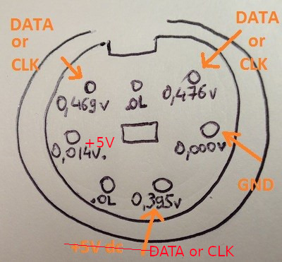
The "GROUND" assignment of the +5V pin in the first post happened, because the internal resistance / leakage current on the unpowered 5V rail is low enough to make the meter beep in continuity test mode. The 38 Ohm measurement clearly shows that this pin is not ground. 30-70 ohms is a common measured value on +5V on AT main boards.
biessea wrote on 2023-05-03, 17:07:So my friend you suggest me to modify the ps2 connector in one of mine keyboards removing the plastic plug, amd that's all?
Not on a keyboard. On a PS/2 extension cord. Like this product: https://www.amazon.de/Goobay-Tastatur-Maus-Ve … r/dp/B000YIVN4A
Modifying a keyboard does a permanent change to the keyboard. An extension cord is disposable and you can leave your keyboard intact.
biessea wrote on 2023-05-03, 17:07:Probably replace the 7 pin connector that it's on now with a ps2 connector could be the best way isn't it?
If a 6-pin socket does fit, it could be a very good option. We don't know whether a 6-pin socket fits.
biessea wrote on 2023-05-03, 17:04:bogdanpaulb wrote on 2023-05-03, 16:57:The if the measurements from first page are correct (please make sure again), this should be the pinout.
I can confirm the measurements.
Please measure the voltage on the pin I and bodganpaulb disagree on. (Meter in voltage mode, red wire on that pin, black wire on the screw nut for GND, computer turned ON). If it is 12V, do not do as I suggested, because that would destroy your keyboard. If it is 5V, my suggestion is OK. If it is 0V, bodganpaulb is likely right that this pin is not +5V.