Thanks Deunan and Horun.
I did it!
Step by step:
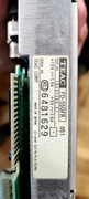
- Yes, BIOS says it's a 1.2Mb unit
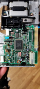
- the I jumper must be ON to get it working 300 rpm or 360 rpm (depending on the HD signal). Deunan, your drive works with HD floppies in DOS? It seems to be configured to get ALLWAYS 300 rpm, I'm a bit confused about it.
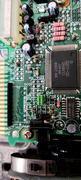
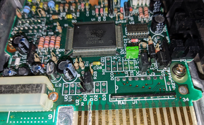
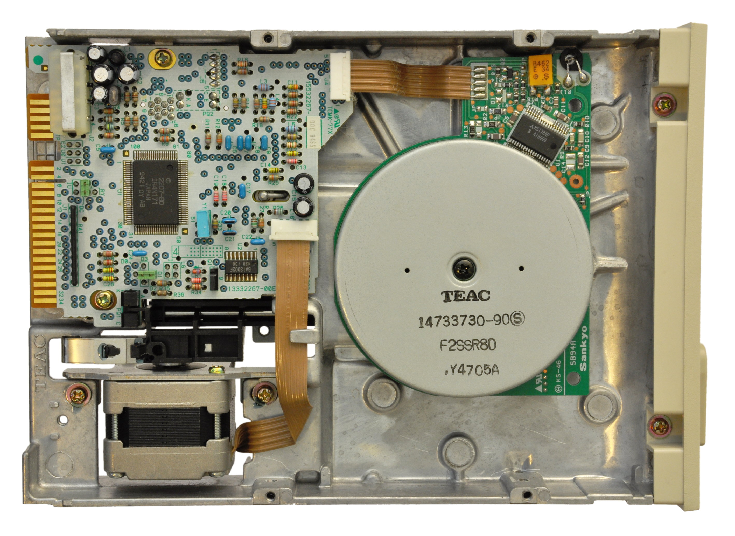
- The top left jumper it's not necesary in my unit, the Ov signal is attached to the frame by the 'R1 thing'.
- I coundn't find any information about S1 to S4, no idea about what are they for... but you were pretty close.
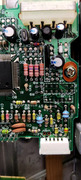
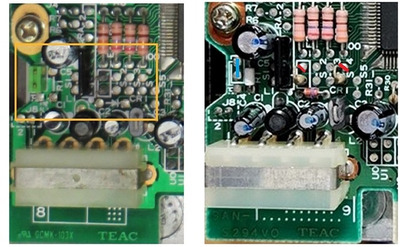
The first resistor you proposed to cut is not S1 (yes, S1 is far away from S2, just on the left of the 'black thing') is E2,
In retrocomp.de info you could find:
Set the E2 strap to the ON state only if your computer requires MASKING THE INDEX. (i.e. PC and older PC/XT that do not give the drive enough time to reach a ready state when the disk replaced.
I cut this resistor and BINGO! Everyting works!
The other problem was in my floppies, straight from the 80's, the only HD floppy (I guess) is not labeled and HANGS the computer as I try to read it. The DD ones work fine.
