VOGONS


First post, by tonata

User metadata
Rank Newbie
Rank
Newbie

Hello,

The barrel battery has damaged the paths, so now I am doing a reconstruction.
I am not sure my reconstruction is correct. Please see below.

- I do not now for sure pins 1,2,3 are for external/internal battery, but I assume so
- the part in green has been damaged, so I am not 120% sure to what pins 2 and 3 are connected, but it seems like in my photo below
- from photos on the internet I see that pins 2 and 3 are connected
- I assume that pins 2 and 3 are for the internal battery
- I have measured 5V as shown on the photo
- Pin 1 is connected to GND

Questions:
- Is the line after d2 the BIOS?
- Does the green part seems OK?
- Why is d1 in this direction? It is if you put the battery inverted +/-?
- Pins 1 and 2 should be to enable external battery ?, but they are GND and 5v so they will make short circuit, so maybe you are not supposed to connect them ... but then why there is this possibility?
Attachments

Reply 1 of 24, by Deunan

User metadata
Rank Oldbie
Rank
Oldbie
tonata wrote on 2023-05-17, 08:10:

- I do not now for sure pins 1,2,3 are for external/internal battery, but I assume so

Is this the mobo you are repairing? https://theretroweb.com/motherboards/s/auva-c … -p8-cpm25-p8-cp

In general the external battery connector is 4 pin, not 3, but one pin is often unused. Your general idea about how it works is correct. There must be a diode (D2 in your case) that prevents feeding 5V back to battery when the mobo is powered, and another diode (D1) is used, with a current limiting resistor, to charge the battery (if it is a rechargeable one). External, non-rechargeable battery would be connected between pins 1 and 3 in your case. No jumper between 2-3 for that, obviously, but yes, it would be needed for internal battery, otherwise it would be drained all the time, even with power applied (but there are some mobos with lithium cells that have such configuration).

Pin 3 is not connected to "BIOS" but rather RTC/NVRAM chip, in your case it's already integrated into chipset but there might be a 4069 that works as 32kHz crystal oscillator, this chip would be then powered by the battery as well.

A word of caution, if your schematic is correct then you have no extra protection diode for the external battery, so be careful not to connect it the wrong way around. On the plus side this allows you to use a lithium coin cell pf 3V or a pack of just two AA/AAA cells as the external battery, because there is no voltage drop of the extra diode.

Reply 2 of 24, by tonata

User metadata
Rank Newbie
Rank
Newbie

Yes, this is my board. Thanks a lot! I do not know how I did not find it before.

1) So P1 is the pins I have pictured. So P1 is only to reset the BIOS not to switch between external/internal battery. Makes perfect sense now.
2) So it was probably a rechargeable battery? I do not have the original battery to check.
3) J7 is the external battery connector (P1 is the BIOS reset) . Are you talking about it when you say pin 4? I think the + is in the direction of the memory (first pin) and the gnd is in the direction of P1 (last pin) as pictured here: https://theretroweb.com/motherboard/manual/31443.pdf. Is that correct?
4) This is the thing!!! I have the 4069 removed by someone. I have ordered it - GD4069UB (CD4069UBE) CMOS Hex Inverter Original GoldStar IC 4069 IC.
5) The keyboard is not working and I think it is because of the the missing 4069.

Reply 3 of 24, by Deunan

User metadata
Rank Oldbie
Rank
Oldbie
tonata wrote on 2023-05-17, 13:24:

3) J7 is the external battery connector (P1 is the BIOS reset) . Are you talking about it when you say pin 4?

Yes, that is the external battery connector, usually it takes the battery terminals on the two outside pins. You can easily check which is GND with an ohm meter - and in fact you should, never assume these connectors are oriented the same way between various mobos.

tonata wrote on 2023-05-17, 13:24:

4) This is the thing!!! I have the 4069 removed by someone. I have ordered it - GD4069UB (CD4069UBE) CMOS Hex Inverter Original GoldStar IC 4069 IC.
5) The keyboard is not working and I think it is because of the the missing 4069.

One of these inverter gates tend to be conneted to reset lines on the mobo, in that case with missing 4096 you might be getting weird random issues due to some chips not being reset properly. The keyboard not working could be related to that but more often then not the issue with keyboard is battery spill and corrosion of the traces. If there doesn't look to be any damage of that kind then perhaps the fuse (F1 next to keyboard socket) is open - this can happen if there is a short in the keyboard between 5V and GND. For a quick test you can bypass the fuse with a piece of wire.

Reply 4 of 24, by tonata

User metadata
Rank Newbie
Rank
Newbie

Thank you! Yes. I failed to explain that my problem was indeed random issues with the motherboard. In the beginning it I thought it wont't boot and then it gradually got better like 50% of the cases.

1) I think what fixes the problem currently is that I added 5V and a 3.8V 18650 battery with wires. Seems stable for now. The 18650 is only fo testing now. So I think the most important is that the BIOS/CMOS line is powered.
2) Currently I got the 5V from one of the legs of keyboard bios chip. I can not attach (too damaged) to the original 5V that are on my schematics above. Not sure where should I get 5V with a wire from the motherboard. I mean what is the best option?
3) I will try bypassing the fuse. Is this dangerous for the motherboard if there is a short circuit or you mean there was temporally - enough to make the fuse open?

Reply 6 of 24, by Deunan

User metadata
Rank Oldbie
Rank
Oldbie
tonata wrote on 2023-05-18, 06:53:

1) I think what fixes the problem currently is that I added 5V and a 3.8V 18650 battery with wires. Seems stable for now. The 18650 is only fo testing now. So I think the most important is that the BIOS/CMOS line is powered.
2) Currently I got the 5V from one of the legs of keyboard bios chip. I can not attach (too damaged) to the original 5V that are on my schematics above. Not sure where should I get 5V with a wire from the motherboard. I mean what is the best option?

Some older mobos require a jumper to be set to control whether the battery is charged or not, on most however this is not required - the on-board battery is assumed to be rechargeable and any external one is not rechargeable. Later 486+ mobos had the RTC and its clock generator in the chipset and the power draw was so low that even a non-rechargeable coin cell will last for years, so they don't have a recharge circuit at all.

Unless more parts were removed from your mobo there is usually no need to add any wires to feed the 5V to the RTC/NVRAM. If the external battery does work and keeps the clock and settings then it's good enough - even if the mobo would not use the 5V at all, and drain the battry even when powered on, it's not going to be your "daily PC". So it won't be on every day for hours. So the battery will drain faster than usual anyway, therefore having it as the only thing that powers the NVRAM is not a big deal. And this might be safer than trying to come up with a wire repair and risk feeding 5V back to the battry with no current or voltage limiting.

tonata wrote on 2023-05-18, 06:53:

3) I will try bypassing the fuse. Is this dangerous for the motherboard if there is a short circuit or you mean there was temporally - enough to make the fuse open?

You can use a very thin wire or solder a 500mA fuse in there - in general most keyboards are well behaved and won't cause any problems. Some mobos have no fuse at all. Some more modern ones have a polysilicon fuse (self-resetable). If you only connect known good keyboards (and only when the mobo is powered off) then a "wire fix" shouldn't be a problem.
This fuse can go open for various reasons. Could be not rated properly from the start and the multiple power-on events, and charging any capacitors in the keyboard, could've killed it eventually. Maybe a pet chewed on the keyboard cable. Or someone tried a device that used keyboard port for power. Or just made a short installing the mobo in the case. No way to tell now but I wouldn't be too worried about it - but just in case you should use a thin wire for this repair.

Reply 7 of 24, by tonata

User metadata
Rank Newbie
Rank
Newbie

Thank you!

Did you see my message that there is no fuse indeed? The F1 place my board is empty.

Here are two images of the board from the internet:
https://cdn.aukro.cz/images/sk1590685168352/p … e-77364877.jpeg
https://a.allegroimg.com/s1024/0cd669/52beed3 … c6dcd9c1e46b232
They both have fuses.
So what does this mean? Removed or it was never installed?

Reply 8 of 24, by Deunan

User metadata
Rank Oldbie
Rank
Oldbie

I'd say removed. If this is the same mobo then, without some mod to bypass the fuse, there won't be 5V power on the keyboard port. If in doubt it's easy to check that, just measure the voltage on pin 5 (do note that DIN pin numbering is a bit weird). No 5V on that pin means the keyboard won't work.

EDIT: Since the missing parts are around the battery I would assume someone removed them to look for broken connections / corrosion, but gave up and never put them back. Or the mobo was stripped for parts (but it's easier to buy a new 4069 than desolder one from multilayer PCB) - which had to be done a long time ago since these days any booting 386 mobo can be sold for some money, even if it has some problems.

Reply 10 of 24, by Deunan

User metadata
Rank Oldbie
Rank
Oldbie

Yes. I figured you'd want to test it right away to know if it's the missing fuse or not - I would. Since you haven't (?) then perhaps get a real fuse (something 500mA to 1A) if you are not comfortable with a wire.

Reply 12 of 24, by Deunan

User metadata
Rank Oldbie
Rank
Oldbie

Fuses are rated for nominal current. The voltage rating is only the breakdown voltage, in fact not even that, more of a safety indicator. Higher voltages need more gap/separation so the fuse will be bigger. So since this is a 5V circuit any fuse will do.

Reply 13 of 24, by tonata

User metadata
Rank Newbie
Rank
Newbie

Here are some photos of the fuse location.
I can not say with 100% confidence it was removed. But logically it looks like that.

Attachments

Reply 16 of 24, by tonata

User metadata
Rank Newbie
Rank
Newbie

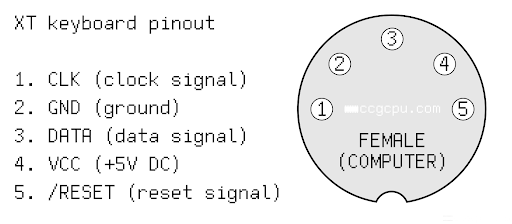
I checked the pins of the keyboard connector.
I am using this schematics:
FEMALE_DIN_5_Keyboard_Connector.png

Pin 1 clk gives 5 V ... shouldn't be 2.5 for example (5/2)? I also tested with logic probe and it is definitely 5V, not a pulsing signal. Maybe because the keyboard is not initialized?
Pin 3 data gives 5V.

The external (towards the out of the motherboard) pin of F1 is connected to L1 and it gives 5V.
The internal pin (towards the inside of the motherboard) is connected to pin 4 of the keyboard connector VCC.
Pin 4 VCC is 0V as expected.

So it seems just making a fuse like connection should power on the keyboard.

Reply 17 of 24, by tonata

User metadata
Rank Newbie
Rank
Newbie

It works!!!!!!!!!!!!!!!!!!!!
I found my 0.5A fuses. I soldered one and the keyboard works.
As long as the CMOS line is powered it works.
The only mystery is why it works without the 4069? It seems it is not important.
Thank you Deunan!!!

I am going to solder a 14250 socket. The CMOS will be powered only by a battery. Not a problem. I will add a cable between the + of the battery and the diode before the CMOS line.

What is the 4069 is doing indeed?