VOGONS


First post, by vintageGuy81

User metadata
Rank Newbie
Rank
Newbie

Hello All,

This is a first for me I think, as I grew up with the old hardware (8086 - 486, Pentium 2 was out by the time I graduated high school) and found something interesting on a Pionex 486 desktop I bought recently.
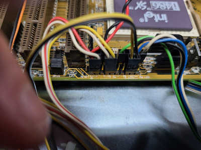
The machine needed quite a bit of cleaning, so I had stripped the machine down, scrubbed the chassis, wiped down all the boards, cleaned out the PSU, lubed the fan and put everything back together.

During the 'orientation' phase where I see how it behaves (just observation of POST, trying to get it to boot for the first time, etc.) I noticed that the Turbo LED was on all the time. While in an error condition during POST, the Turbo button didn't make the LED turn off. I thought they responded no matter what phase of bootup you were in (based on the fact that I never really paid attention until now). When clearing the error condition and booting, the turbo button doesn't seem to do anything except if you engage it, then release it within a few seconds after engaging it.

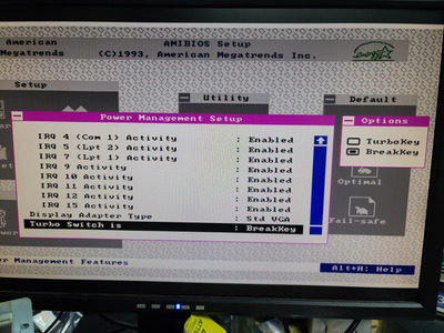
The screen goes blank, and the turbo button begins to blink with a steady cadence if you push the turbo button in then push it again to 'switch off' the switch. If you hit anything on the keyboard, the screen comes back to where you were when the turbo button was pressed, and the turbo LED stops blinking and comes back on steadily. I have never seen this behavior before. It looks like a sleep mode. I'm still waiting on parts to be able to boot consistently (the floppy drive that came with the machine is shot, and I have a new bracket for the IDE to CF adapter I installed, but don't like its orientation), so once I'm able to boot maybe I can play around with it more. I skimmed the bios settings, and all I saw related to the speed was what speed to select on startup (High or low).

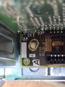
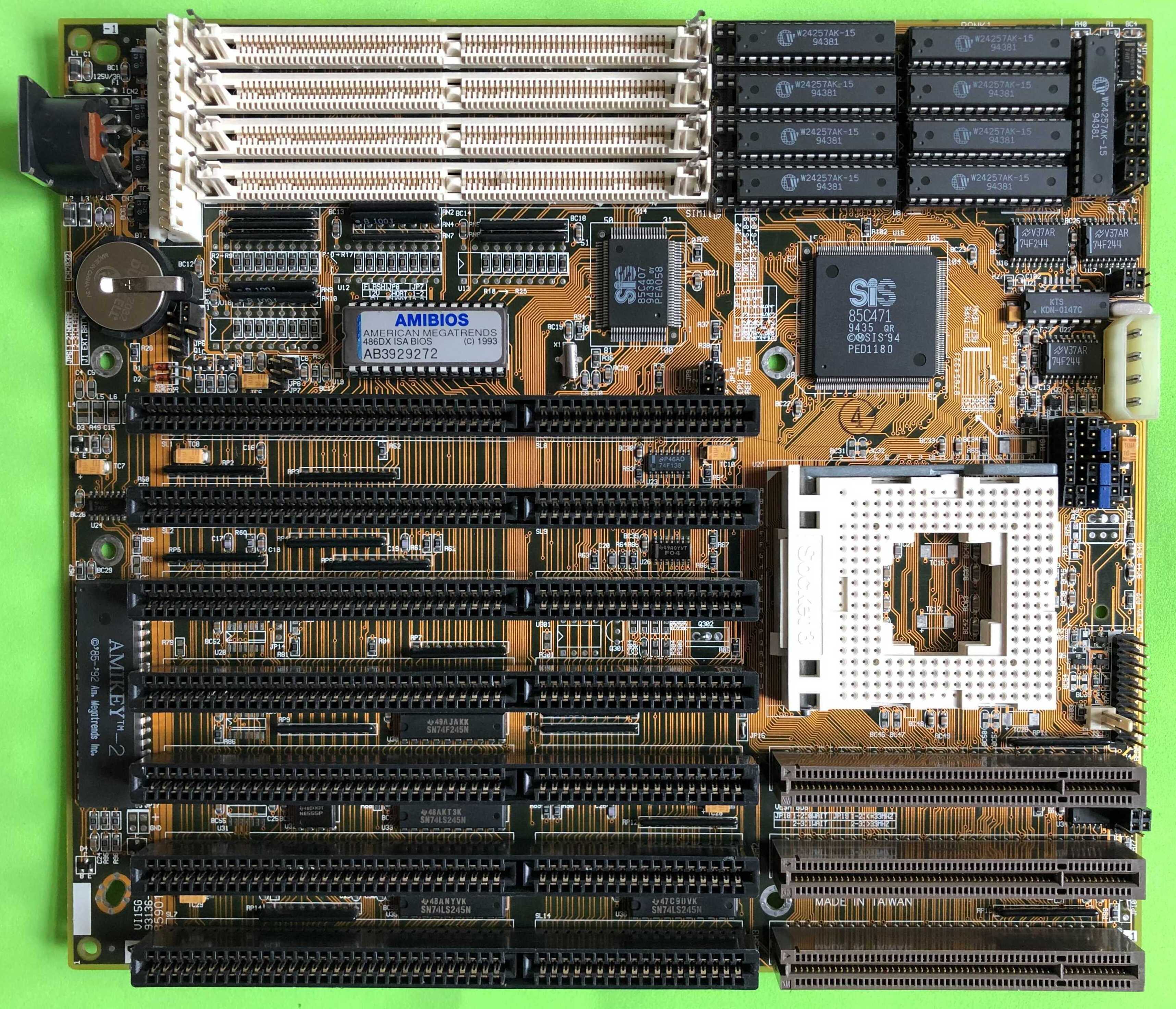
The board has a SiS chipset on it but I don't know if SiS is the board manufacturer yet. Intel 486 SX/33 processor. ISA and VLB slots. the AMI chip says "486DX Bios" on it. (Nothing unique, seems pretty standard)

Has anyone else seen this kind of behavior? Thanks for reading!

Reply 1 of 12, by Tiido

User metadata
Rank l33t
Rank
l33t

Sounds like the button and LED are wired to "Green switch" and indicator, which basically is a sleep kinda deal. See where exactly do the switch and LED connect to on the motherboard.

T-04YBSC, a new YMF71x based sound card & Official VOGONS thread about it
Newly made 4MB 60ns 30pin SIMMs ~
mida sa loed ? nagunii aru ei saa 😜

Reply 2 of 12, by vintageGuy81

User metadata
Rank Newbie
Rank
Newbie
Tiido wrote on 2023-05-30, 12:03:

Sounds like the button and LED are wired to "Green switch" and indicator, which basically is a sleep kinda deal. See where exactly do the switch and LED connect to on the motherboard.

Thanks! The pins are labeled "TB SW" and "TB LED" on the motherboard, but I can definitely look more closely. I took pictures of the arrangement before I disassembled for cleaning, maybe they were wrong even before I took ownership of the machine? There are two rows in the pin header, maybe those labels are meant for the row above.

Reply 3 of 12, by Tiido

User metadata
Rank l33t
Rank
l33t

Ok, labelling would suggest that they do go into the right place, but the observed behaviour suggests otherwise. But the second row is worth looking at.

What motherboard is in the machine ? Do you have photos ? You might be able to find it here along with some documentation : https://theretroweb.com/

T-04YBSC, a new YMF71x based sound card & Official VOGONS thread about it
Newly made 4MB 60ns 30pin SIMMs ~
mida sa loed ? nagunii aru ei saa 😜

Reply 4 of 12, by vintageGuy81

User metadata
Rank Newbie
Rank
Newbie
Tiido wrote on 2023-05-30, 12:25:

Ok, labelling would suggest that they do go into the right place, but the observed behaviour suggests otherwise. But the second row is worth looking at.

What motherboard is in the machine ? Do you have photos ? You might be able to find it here along with some documentation : https://theretroweb.com/

Thanks Tiido, I ran down stairs to look, and found the model number. Looks like an AOpen VI15G. (I didn't get a whole board shot because IDE/floppy cables and expansion cards are in the way) but if I had to compare it to one of the models on the link you shared, it's this one:

https://theretroweb.com/motherboard/image/mb- … ea251100338.jpg

It even says VI15G on the photo in the link above. I'll take pictures of the pin header once I'm done with work

Attachments

Reply 5 of 12, by wiretap

User metadata
Rank Oldbie
Rank
Oldbie

It looks like the turbo switch / turbo LED pins are dual purpose.. one use for energy efficient sleep, and the other for turbo functionality. Did you check the BIOS to see if there are any green/sleep/power options you can disable?

My Github
Circuit Board Repair Manuals

Reply 6 of 12, by Thermalwrong

User metadata
Rank Oldbie
Rank
Oldbie

Yeah, I was checking the BIOS on my Via chipset 486 SBC with an Award BIOS yesterday.

It does have a setting in there for Turbo button behaviour, which switches between turbo and sleep/green modes.

Reply 7 of 12, by vintageGuy81

User metadata
Rank Newbie
Rank
Newbie
wiretap wrote on 2023-05-30, 17:04:

It looks like the turbo switch / turbo LED pins are dual purpose.. one use for energy efficient sleep, and the other for turbo functionality. Did you check the BIOS to see if there are any green/sleep/power options you can disable?

Hey wiretap,

I checked just now. You can set it as "TurboKey" or "BreakKey" as shown in the attachment. When I set it to Turbo Key, the sleep behavior stops when I push the turbo button.
However, the turbo LED stays on no matter what. Not sure if it's readable, but I attached a pic of the pin descriptions on the board. Looks like the turbo switch could be 3 pin unless they planned a space pin between the switch and LED. I moved the LED pin header around, went to the right edge and saw the yellow LED light up with a red hue, so I figured one of the pins may have been 5r volts or more, so I removed it. Then I went to the left and strapped the next two pins after the turbo switch pin header and saw the turbo LED lit, but at half brightness. In addition, if I actuate the turbo switch while the LED is on the pins right next to the turbo switch (which would put it within what I think is a third pin for the turbo switch), the LED turns off when the switch is pushed in.

I'll be looking for documentation, but from what I can tell from this site and others, this board is a little weird. Thanks so much for the interaction thus far all of you. I'll keep everyone posted as I poke around.

Attachments

Reply 8 of 12, by vintageGuy81

User metadata
Rank Newbie
Rank
Newbie

Hey All, just a small update:

I did a Google search this morning for "Acer vi15g" instead of AOpen, and found this page:

https://stason.org/TULARC/pc/motherboards/A/A … -486-VI15G.html

It has pinout information that differs from what I see being used in my particular machine. I don't know if I'm allowed to post a screen cap of the diagram shown at the link above, but it shows J4 as being 20 pins, pins 1-10 on the edge of the motherboard and 11-20 above it. If you rotate it left 90 degrees that would be the view I see while it's installed in the case. That would put pins 1-10 on the bottom row, and 11-20 on the top row.
This conflicts because the PC speaker, for example, says pins 6-10, and if I'm interpreting the numbers on the diagram correctly, that would put it on the bottom right of the pin header. My machine has the PC speaker on the top left, and it's functioning.

They also mention the turbo switch pins, but they also have "green PC break" in parenthesis. So I'm guessing wiretap nailed it, the turbo switch must be dual purpose. I wonder if there is a way to make it behave as a normal turbo switch. My first step will be to check all of the pin positions on the board. I'll compare it to the diagram and see if I can confirm if the turbo LED and switch are in the right position. If the positions are okay, then I guess I'll pay attention once the O/S is installed and I run an application to observe speed with the two positions of the turbo switch...

Reply 9 of 12, by vintageGuy81

User metadata
Rank Newbie
Rank
Newbie

Just a quick update...

I verified the position of the turbo switch using the text description of the pins from the link in the above post, as well as the other features. I installed a new old stock CPU cooler/fan combo because I don't remember if SX/33 really needs it. Probably not, but I wanted to make sure it was taken care of. I installed a 1Gb CF card on a StarTech CF to IDE adapter, and installed an ATAPI CD-ROM drive. Loaded MS DOS 6.22, ESS 1868/1869 drivers, OAKCDROM.SYS and a mouse driver.
The machine is stable. The Turbo LED still does not change state with the position of the turbo switch. The bios reports 33Mhz, but the overall performance of the machine is slower than an Acer Acros 486 SX/25 I have. I don't know if it is a clock speed issue, or if it needs more cache to be faster (there are two banks of chip sockets for cache and only one bank is populated (256k))

For all the fighting and challenges this machine gave me, I'm a bit disappointed in its performance. I might take a look into it further, or I might sell it. Not sure yet. It's fully restored, the case cover painted (poorly), the front bezel de-stained, the entire case scrubbed, power supply pulled apart and dusted, circuit boards wiped down, and new CPU cooler and fan that were not in it at time of purchase. It's an old Pionex. I don't even know if this AOpen/Acer board is original. I can post pics if anyone is interested, but I do REALLY appreciate all the communication on this thread. I've learned and had a great time chatting about it. Thanks for all the info and participation!

Reply 10 of 12, by steevf

User metadata
Rank Newbie
Rank
Newbie

What IDE controller card did you have for that Acer Vi15G? The reason I ask is I'm have a lot of instability issues with the same motherboard involving the IDE interface. Every once in a while the HDD just disappears. The IDE card I got is DTC 2278E VLB. It's odd that it came with this computer because the BIOS doesn't seem to support the second IDE controller and this IDE card doesn't have it's own BIOS on it. It's also the FDD controller and the Serial/parallel/game port controller.

Reply 11 of 12, by vintageGuy81

User metadata
Rank Newbie
Rank
Newbie
steevf wrote on 2024-02-12, 22:04:

What IDE controller card did you have for that Acer Vi15G? The reason I ask is I'm have a lot of instability issues with the same motherboard involving the IDE interface. Every once in a while the HDD just disappears. The IDE card I got is DTC 2278E VLB. It's odd that it came with this computer because the BIOS doesn't seem to support the second IDE controller and this IDE card doesn't have it's own BIOS on it. It's also the FDD controller and the Serial/parallel/game port controller.

I'll have to find the card and see if I can find the model number on it. It was a single IDE/floppy/RS232 if I remember right, 16-bit ISA. Never had trouble with the I/O, the board was just bloody slow. I traded it for a Shuttle board with a P100.

Reply 12 of 12, by BitWrangler

User metadata
Rank l33t++
Rank
l33t++

A few Asus boards implement turbo switching with ctrl-alt and the numberpad +/- keys, so you could see if that soft switching changes turbo light. There might be a further setting elsewhere in the CMOS setup to ignore the turbo button... some BIOS had that, and if they could have left that in, but also added the green break setting.

Unicorn herding operations are proceeding, but all the totes of hens teeth and barrels of rocking horse poop give them plenty of hiding spots.