VOGONS


First post, by dogwomble

User metadata
Rank Newbie
Rank
Newbie

Hey all,

I wanted to try and get a little bit of guidance on this, as it seems information on this is a little bit scattered and contradictory.

I am about to embark on restoring an old 486. One of the issues I was planning on tackling was the BIOS battery, as it's dead. Thankfully this wasn't using a CR2032, it was using a separate battery via PIN header, which was an old 3.6v lithium. This at least means it hasn't spewed its guts all over the motherboard.

I did have a thought, and bought parts for, a 3xAA battery holder that I could graft onto the existing connector as a cheap and dirty way to use some existing AA batteries that I have. The only issue is that I would then be feeding it 1.5 volts, as each of my AA's does 1.5 volts. This may be too much voltage. Another alternative would be possibly using some rechargeable batteries which typically run at 1.2v, but these can be quite a bit more expensive.

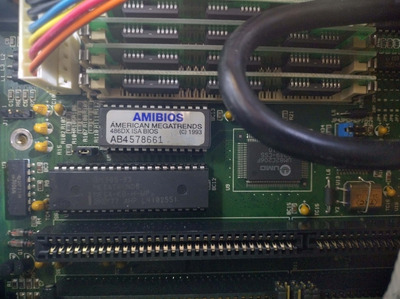
Before I take the plunge with either of these options, I'm wondering if anyone has experience with running their BIOS chips at higher voltages. If it helps, it is an AMI BIOS chip - I am hoping to try and avoid peeling the label off to identify the specific chip they've used, because that would be a PITA.

Reply 1 of 16, by Horun

User metadata
Rank l33t++
Rank
l33t++

Post a picture of the motherboard or give us the make/model. Most are designed for an onboard 3.6v/3.7v (if not a coin cell) and with 4.5v offboard. I have used 3-AA as external on lots of older 286, 386, 486 with out issue on those 4 pin external battery connectors...

Hate posting a reply and then have to edit it because it made no sense 😁 First computer was an IBM 3270 workstation with CGA monitor. Stuff: https://archive.org/details/@horun

Reply 2 of 16, by majestyk

User metadata
Rank Oldbie
Rank
Oldbie
dogwomble wrote on 2023-06-23, 12:58:

... Thankfully this wasn't using a CR2032, it was using a separate battery via PIN header, which was an old 3.6v lithium.

It won´t get any better than a CR2032, because these lithium cells are extremely stable and reliable over time - as opposed to NiCd cells of Varta fame.

When you want to use your old AA cells and be on the safe side just insert 2 of them (and bridge the 3rd chamber), you get 3V output and this will be enough to retain your CMOS data.

Reply 3 of 16, by wiretap

User metadata
Rank Oldbie
Rank
Oldbie

If you look up the spec sheet of the RTC IC on the board, it will tell you what input voltages it cuts off at, both min and max. You'll also have to check to see if there are any diodes in circuit (which there usually are) to calculate any other voltage drops.

My Github
Circuit Board Repair Manuals

Reply 4 of 16, by dogwomble

User metadata
Rank Newbie
Rank
Newbie
majestyk wrote on 2023-06-23, 13:43:
dogwomble wrote on 2023-06-23, 12:58:

... Thankfully this wasn't using a CR2032, it was using a separate battery via PIN header, which was an old 3.6v lithium.

It won´t get any better than a CR2032, because these lithium cells are extremely stable and reliable over time - as opposed to NiCd cells of Varta fame.

When you want to use your old AA cells and be on the safe side just insert 2 of them (and bridge the 3rd chamber), you get 3V output and this will be enough to retain your CMOS data.

That would probably be a wise idea 😀

The board is a little obscure. The board is made by an Australian clone manufacturer - IPEX IPX-UM-4861V6201. There doesn't seem to be a lot of information I could find on that board specifically, other than it seems to be a version of this board - https://stason.org/TULARC/pc/motherboards/U/U … -486-VL486.html.

I'm not sure if this will help much, as the label is covering the actual chip itself, but I've managed to get an image of the actual BIOS chip. I was having a quick look last night to try and work out how easy it would be to remove the label to try and identify the chip underneath, it might be a challenge because it's fairly well stuck on. I could probably try and find ways to remove the sticker without damaging the chip, but if it's something somebody can quickly identify first that might be the easier option.

My main reason for asking is that I seem to get a mix of information for PC's of about this vintage - some seem to think it's fine, others not so, so I am suspecting it's very machine dependent. My electronics knowledge is a lot more primitive than my PC knowledge, so I'm wanting to try and get a better understanding of how this works before I do something stupid. 😀

Attachments

Reply 5 of 16, by Horun

User metadata
Rank l33t++
Rank
l33t++

You are confusing the hardcoded BIOS chip with what stores the Settings, which would be in the main chipset or some other special chip (like a Dallas rtc).
Does the whole board look like this: https://theretroweb.com/motherboards/s/ecs-vl486 ?

Hate posting a reply and then have to edit it because it made no sense 😁 First computer was an IBM 3270 workstation with CGA monitor. Stuff: https://archive.org/details/@horun

Reply 6 of 16, by dogwomble

User metadata
Rank Newbie
Rank
Newbie
Horun wrote on 2023-06-24, 02:10:

You are confusing the hardcoded BIOS chip with what stores the Settings, which would be in the main chipset or some other special chip (like a Dallas rtc).
Does the whole board look like this: https://theretroweb.com/motherboards/s/ecs-vl486 ?

Yeah, that's fair 😀 I don't normally work with boards at this level, so it appears I need to learn a few things.

That layout does look about right.

Reply 7 of 16, by jakethompson1

User metadata
Rank Oldbie
Rank
Oldbie
majestyk wrote on 2023-06-23, 13:43:

When you want to use your old AA cells and be on the safe side just insert 2 of them (and bridge the 3rd chamber), you get 3V output and this will be enough to retain your CMOS data.

My experience has been that a CR2032 (3V) on many boards is enough to hold the settings, but the voltage is too low to run the clock. It freezes while the machine is off.

To the OP, 4.5V may be just right for your board. This is what was actually connected to the external battery header: https://i.ytimg.com/vi/0PZLKfsDlB8/maxresdefault.jpg
I read somewhere about someone opening one up, and it was the same six cells as inside a 9V battery, but broken into two groups of three connected in parallel.

Reply 8 of 16, by Horun

User metadata
Rank l33t++
Rank
l33t++

Agree Jake !
for the OP: OK so the CMOS is located in the 82C206 UMC chip, I see two diodes not far below the 4 pin Ext. battery connector. Those would be for dropping voltage from battery (6v-1.4v= 4.6v) and make sure it is not back charged.
From the prelim spec sheet it recommends 6volt (page 6-49, and figure 10 on 6-50). http://bitsavers.trailing-edge.com/components … mc/UM82C206.pdf
Using 3 x AA will not hurt at all and is better than a 3.7v battery on same external battery connector and does not exceed the 6.7v limits based on page 6-58 for the cmos.....

Hate posting a reply and then have to edit it because it made no sense 😁 First computer was an IBM 3270 workstation with CGA monitor. Stuff: https://archive.org/details/@horun

Reply 9 of 16, by DaveDDS

User metadata
Rank Newbie
Rank
Newbie
dogwomble wrote on 2023-06-23, 12:58:

I did have a thought, and bought parts for, a 3xAA battery holder that I could graft onto the existing connector as a cheap and dirty way to use some existing AA batteries that I have. The only issue is that I would then be feeding it 1.5 volts, as each of my AA's does 1.5 volts. This may be too much voltage. Another alternative would be possibly using some rechargeable batteries which typically run at 1.2v, but these can be quite a bit more expensive.

3 x 1.5v = 4.5v - this may be OK for your RTC chip, maybe not - check the chip specs to be sure.
Also, the mainboard may "charge" slowly which might not be good for typical AA cells.

NiCad/NMIH is nominally 1.2 x 3 = 3.6v - but these cells don't do well in constant charge very low discharge cycles (like an RTC).
Also they do "ride high" a bit right after a charge, so you may see higher voltage at times.

I often use "supercaps" to replace old RTC/CMOS batteries - but be aware that often the "charge" circuit "counts on"
the original NiCads to limit it's (higher) voltage - Any sort of capacitor has no such limitation and can
charge to whatever the charging circuit supplies (many charging circuits are higher voltage and rely on series
resistance to both provide a very low charge current and "bleed off" voltage higher than the native
battery allows.

Diodes can help - they have a "voltage drop" before they start conducting.
A LED for example often has around 1.8v drop - a typical rectifier diode usually has
about 0.7v drop - I recently swapped out a deceased 3 NiCad board mounted pack (~3.6v) in an
old TRS-80 Model100 with some caps and a couple LEDs and rectifier diode in serial across it
to drop extra current once past about 4.3ish v which is well within the chip specs as they
switch to 5v once the unit is turned on.

Dave Dunfield ::: https://dunfield.themindfactory.com
or: "Daves Old Computers" -> Personal (near bottom)

Reply 10 of 16, by jakethompson1

User metadata
Rank Oldbie
Rank
Oldbie
DaveDDS wrote on 2023-06-24, 02:53:

3 x 1.5v = 4.5v - this may be OK for your RTC chip, maybe not - check the chip specs to be sure.
Also, the mainboard may "charge" slowly which might not be good for typical AA cells.

What's the best way to check whether an external battery header charges? Try connecting a LED across it (both directions) and see if it lights, or check voltage with a multimeter?

Reply 11 of 16, by Horun

User metadata
Rank l33t++
Rank
l33t++

I say an LED. Voltages can be odd. Even with diodes you could get a bad V reading when basically no current can flow when reverse biased.....but the volts think so 😀
added: An old true analog Voltmeter would tell you but the the newer DIgi ones are so sensitive they can even pickup stray volts that really do not exist under any load....

Hate posting a reply and then have to edit it because it made no sense 😁 First computer was an IBM 3270 workstation with CGA monitor. Stuff: https://archive.org/details/@horun

Reply 12 of 16, by Kekkula

User metadata
Rank Newbie
Rank
Newbie

My experience has been that a CR2032 (3V) on many boards is enough to hold the settings, but the voltage is too low to run the clock. It freezes while the machine is off.

I just replaced nicd battery from old 286 board with cr2032, and noticed that it does keep the cmos settings but the clock does not keep the time.
I don't mind that the clock doesn't work, but was thinking maybe some programs or games uses the clock?

Reply 13 of 16, by dogwomble

User metadata
Rank Newbie
Rank
Newbie
Horun wrote on 2023-06-24, 02:35:
Agree Jake ! for the OP: OK so the CMOS is located in the 82C206 UMC chip, I see two diodes not far below the 4 pin Ext. batter […]
Show full quote

Agree Jake !
for the OP: OK so the CMOS is located in the 82C206 UMC chip, I see two diodes not far below the 4 pin Ext. battery connector. Those would be for dropping voltage from battery (6v-1.4v= 4.6v) and make sure it is not back charged.
From the prelim spec sheet it recommends 6volt (page 6-49, and figure 10 on 6-50). http://bitsavers.trailing-edge.com/components … mc/UM82C206.pdf
Using 3 x AA will not hurt at all and is better than a 3.7v battery on same external battery connector and does not exceed the 6.7v limits based on page 6-58 for the cmos.....

OK so from the sounds of what you and Jake are saying, I should be very much in the clear with this. This is not necessarily a bad thing. While I could try and get a 3.6v lithium, they seem to be a bit more expensive where I am and I already have some AA batteries I can use. The only question I have now is what I need to do to make sure nothing gets back charged - the header that I've got seems to only have a single cable pair coming out of it, can I get away with throwing a diode or something similar across one of them?

Reply 14 of 16, by DaveDDS

User metadata
Rank Newbie
Rank
Newbie
Horun wrote on 2023-06-24, 03:00:

I say an LED. Voltages can be odd. Even with diodes you could get a bad V reading when basically no current can flow when reverse biased.....but the volts think so 😀
added: An old true analog Voltmeter would tell you but the the newer DIgi ones are so sensitive they can even pickup stray volts that really do not exist under any load....

A LED will work - not knowing what the charge current is .. I'd also add a 220ohm(ish) resistor to limit current,
If you do this kind of thing a lot, a handy little tool you can make is two LEDs back-to-back (opposide polarities) with 220 Ohm in
serial - one LED will light no matter what the polarity (and which one lights will tell you the polarity).

A simple DVM will work even better, positive or negative reading will tell the the polarity, and the
actual open-circuit voltage (which is what a cap would charge to) - also good to measure current
to see how much charge current it provides (best to do this into say a 100 ohm load).

Dave Dunfield ::: https://dunfield.themindfactory.com
or: "Daves Old Computers" -> Personal (near bottom)

Reply 15 of 16, by DaveDDS

User metadata
Rank Newbie
Rank
Newbie
Kekkula wrote on 2023-06-24, 06:36:

My experience has been that a CR2032 (3V) on many boards is enough to hold the settings, but the voltage is too low to run the clock. It freezes while the machine is off.

I just replaced nicd battery from old 286 board with cr2032, and noticed that it does keep the cmos settings but the clock does not keep the time.
I don't mind that the clock doesn't work, but was thinking maybe some programs or games uses the clock?

Just be aware and if the former was NiCad, the system does provide a charge current - a CR2032 is NOT a rechargable battery, and this
change current may cause "bad things" to happen...

But having said that... in my experience many CR-2032 are OK with this .. best to check and see if ANY "reverse current" flows (try with
system both ON/OFF) ...

I came to this with Logitech "Solar" keyboards - they have an ML-2032 inside, which is a rechargable "2032 equivalent"
The problem is ... they are NOT common. Very difficult and pricey to obtain. I made a little gadget to fit the ML-2032 carrier,
with external leads so I could attach a CR-2032 outside - I didn't see any reverse current when the keyboard was off and in
bright sunlight - I then used a 4.5 digit DVM on the 2ma (lowest) scale - (having tested very low currents with it before I know
that is will reliably let me know if a current of > 0.001 ma (a millionth of an amp) flows - when Idle on this setting, random
induced currents cause it to sometimes briefly show 0.000-0.001 but 0.001 ma will make it show 0.001-0.002)
Not seeing any occurances of 0.002 ma I decided to put the CR-2032 in and leave it as is (some others have covered the solar
cells when doing this) - with the cells exposed I've gone several years, a couple of CR-2032s and no problems...

But I'm not saying this will always be ok - you really want to be sure the CR-2032 you choose does not let any reverse (charging) current flow
in the circuit.

- And BTW - if you can get an ML-2032 Don't replace the NiCads with it - completely different changing
requirements -

Dave Dunfield ::: https://dunfield.themindfactory.com
or: "Daves Old Computers" -> Personal (near bottom)

Reply 16 of 16, by Kekkula

User metadata
Rank Newbie
Rank
Newbie

I just cut the trace going to battery + and soldered random diode there.
Just watched Adrian's video and noticed that my 286 board has same clock chip, have to try and replace it with dallas or equivalent 🤔

https://youtu.be/2Sgleturods