Locutus wrote on 2023-07-29, 19:23:
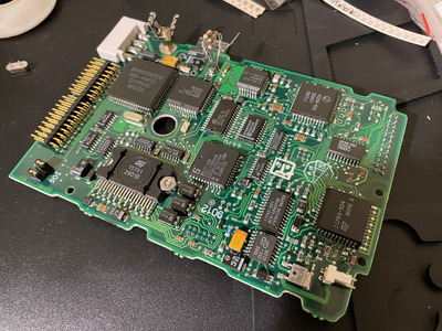
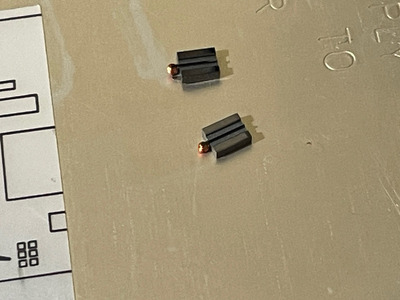
All SMD components appear to be factory fitted (glued and 'same' soldering). I started by replacing them with identical parts (all '0 resistors' were open - question is why...).
I've never seen anything like this. I can only offer some wild theories:
1) these acted like fuses and went open during some serious power event (12V on 5V line, or reverse polarity)
2) went open due to age and manufacturing defects
3) actually were meant to be open, 0 is misleading
1 - That would destroy the electronics and I would think such big resistor and thin traces (like near J6 conenctor) would result in damaging the copper before them going open, or at least there would be some traces of such event (the PCB has plenty of intact tantalum caps)
2 - All of them? Seems... unlikely. I mean it's not exactly difficult to make a 0 ohm resistor of that size, and there is no visible mechanical damage either
3 - That would be misleading but such resistors might be put on to pass automated inspection that looks for missing parts, and yes I realize I'm grasping at straws here
Locutus wrote on 2023-07-29, 19:23:
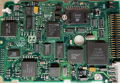
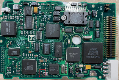
In newer ST-157I, this crystal is 'loaded' witch capacitor through 300 ohm resistor...
Yes, but it's also like that on the photo fromt the page I found (BTW that page opens the image scaled down, download it or copy to some image viewer program and you'll get much nicer photo).
The value is "3010" so 301 ohms I take it. And the date code on that PCB is very close to yours (9027 / 9029). Both cary "106" stamp in the upper right corner where the model/rev print is. BTW the master/slave jumpers there, have you tried removing those? It looks like your current confing is master+slave and the early ATA drives really do not like that if the slave is absent. Weird things happen in such cases, no-spin is one of them.
These 0 ohms are very suspicious, I realize this is partly analog stuff but I have never seen them used like this. Since the PCB doesn't work as-is, why not try putting some resistors that match the other HDD? At least around the crystal chip and maybe the upper-left corner too (it's a stepper servo driver I think?).
