VOGONS


First post, by kinetix

User metadata
Rank Member
Rank
Member

For some time now I am trying to revive my two oldest systems, a 486 (AOpen Vi15G 3.45v version+Am5x86@133) and a Pentium (AOpen AP53+MMX@200). both were stored almost 20 years ago, in a functional state. but after taking them out of the boxes and cleaning them thoroughly, they don't work. On another thread I have managed to discern new information about their jumper settings and other data. but still.

all voltages are OK.

I got a dump form both 486 boards BIOS. I compared both with the 2.3 version published in the RetroWeb and are identical. while reading (with a Dataman programmer) one an error came out on the 486#1 bios chip, something like "Vcc Min validation reading error", or something like that, but it seems to me that it is not a problem as it was read OK. perhaps the surface has a very thin layer of oxidation that creates resistance. The other did not give any error even if it had its pins in bad condition so I need to sanded and scraped them before reading the chip. Edit: today after sanding the pins now the error is on "Vcc Max", but still is readed OK.

the 486#2 board was dirty. I cleaned that one the best as I could put is still slightly rusty on some contacts. It also have a corner (the cache corner) with a slight damaged from fire (an accident in the garage, I lost some hardware), only had the capacitor BC4 almost unsoldered by the heat, but I measured it and it seems ok, as are all the lines.
The 486#1 (my target) and the Pentium are pretty clean.

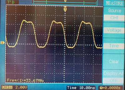
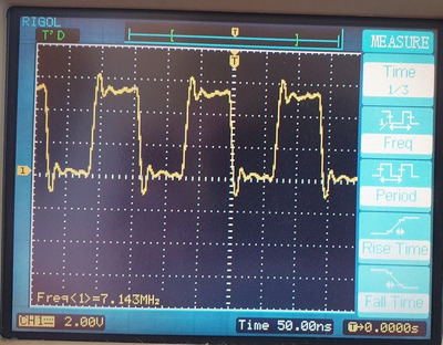
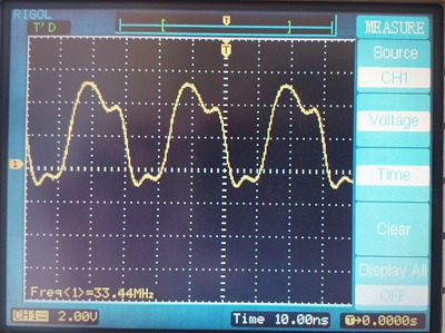
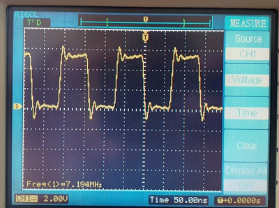
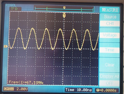
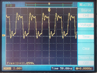
and the next images are what the clock signals on the ISA bus and on the CPU look like. I thin they are "dirty" looking at those spikes. also I think the CPU_CLK signals should be more squared, or am I wrong?.

How good or bad are these clock signals?
are those spikes lack of grounding or some radiointerference? (the power outlet had no ground)
If those are bad, what could be the reasons?

Attachments

  • 486#1-CPU_CLK.jpg
    Filename
    486#1-CPU_CLK.jpg
    File size
    85.48 KiB
    Views
    788 views
    File license
    Public domain
  • 486#1-ISA.jpg
    Filename
    486#1-ISA.jpg
    File size
    87.58 KiB
    Views
    788 views
    File license
    Public domain
  • 486#2-CPU_CLK.jpg
    Filename
    486#2-CPU_CLK.jpg
    File size
    72.79 KiB
    Views
    788 views
    File license
    Public domain
  • 486#2-ISA.jpg
    Filename
    486#2-ISA.jpg
    File size
    83.26 KiB
    Views
    788 views
    File license
    Public domain
Last edited by kinetix on 2024-03-02, 21:51. Edited 4 times in total.

Reply 1 of 14, by kinetix

User metadata
Rank Member
Rank
Member

this one is the Pentium board (AOpen AP53). I forgot to measure the clock in the PCI bus.
need opinion too, although this board is for a latter time is the main interest for me.

Attachments

  • 586-CPU_CLK.jpg
    Filename
    586-CPU_CLK.jpg
    File size
    81.79 KiB
    Views
    778 views
    File license
    Public domain
  • 586-ISA.jpg
    Filename
    586-ISA.jpg
    File size
    88.07 KiB
    Views
    778 views
    File license
    Public domain

Reply 2 of 14, by mkarcher

User metadata
Rank l33t
Rank
l33t

All the clock signals you show don't show any obvious problems with the clock signals.

The ringing you see on the 8MHz clock can be caused by your measuring method: To make sure you get the edge displayed right, the standard alligator clip ground setup is insufficient. A short wire front the end of the scope to a ground pin very close to the clock pin will increase edge fidelity and reduce false ringing. In this case, you get around 0.8V underhoot/overshoot for less than 5ns, so even if the undershoot/overshoot really is present this much, it wouldn't do much damage. ISA is TTL, so everything below 0.8V is "low" and everything above 2.0V is "high", and the time duration between 0.8V and 2.0V in the ISA clock signals is extremely short. That's perfect.

The 66MHz CPU clock looks very rounded. A CPU clock in that shape would be bad. But I suspect you do not see quality issues of the clock signal here, but actually you see the limit of your probing setup. If you measure a 66MHz clock with a probing setup with a bandwidth of around 80MHz (that's the typical bandwidth for current entry level scopes and probes), it will always look this round, even if the clock is perfectly square. Looking at the edge shape of the 33MHz and the 66MHz clocks, they all look consistent with you reaching the bandwidth limit of your setup at 66 MHz, and you are like already seeing rounder edges than ther actually are at 33MHz. That's why I can't tell you that the signals are fine for sure, but only that the probing you used is unable to reveal any serious issues. The 33MHz clocks most likely is perfectly fine indeed. Issues that need a even higher bandwidth to be visible on a scope are so short-term that chips rated for 30-40 MHz clock are not able to see them, just like your scope is not able to them.

The second CPU clock you see seems asymmetric at the first glance. Also, the high level is inconsistent. But considering that the signal is below 0.8V or above 3V most of the time, the wiggling in the low and high part doesn't really matter. The "high" time might be slightly longer than the "low" time, which is not that great, but it still seems to be good enough. The first CPU clock you probed is probably the nicest looking shape your scope/probe can resolve at 33MHz, so it would be very surprising if there were any notable issues at this board.

Reply 3 of 14, by kinetix

User metadata
Rank Member
Rank
Member

thanks for your answer.
I took the ground on the metal part of the keyboard connector, so yes, something away from the clock generator. About the bandwidth limit of the oscilloscope, I don't know, a friend helped me and I didn't ask him, I only remember the measurement limit was 1 GHz. Today I will ask him or I will look in the manual. I can also repeat the measurements with a grounding as close as possible to the clock generator.

Reply 5 of 14, by mkarcher

User metadata
Rank l33t
Rank
l33t

With that probe, you are clearly limited by the scope bandwidth only. So my guess of "around 80 MHz bandwidth" wasn't that far off, as the scope is a 100MHz scope. The "1GHz" specification is the digital sampling rate, not the analog bandwidth.

You don't necessarily have to repeat the measurement, but if you want to see for sure how much of the ringing is real and how much is an artifact, you can do that for educational purpose. Grounding with that alligator clip might prove insufficient at 100MHz bandwidth, even if you connect the clip closer to the clock signal. For highest fidelity measurements, you need a "oscilloscope probe ground spring" (you might want to search google images for the term (without quotes) to see what I mean) connected to a local ground point close to the clock signal. It wouldn't surprise me if a 250MHz probe already includes this kind of spring in the accessory pack supplied with the probe.

Reply 6 of 14, by rasz_pl

User metadata
Rank l33t
Rank
l33t

more on high freq measurements with scope Re: Custom interposer module for TI486SXL2-66 PGA168 to PGA132 - HELP!

your clocks are fine

>On another thread

why not link that other thread? 😀 have you tried POST cards?

Open Source AT&T Globalyst/NCR/FIC 486-GAC-2 proprietary Cache Module reproduction

Reply 7 of 14, by kinetix

User metadata
Rank Member
Rank
Member
mkarcher wrote on 2023-08-11, 17:10:

With that probe, you are clearly limited by the scope bandwidth only. So my guess of "around 80 MHz bandwidth" wasn't that far off, as the scope is a 100MHz scope. The "1GHz" specification is the digital sampling rate, not the analog bandwidth.
You don't necessarily have to repeat the measurement, but if you want to see for sure how much of the ringing is real and how much is an artifact, you can do that for educational purpose. Grounding with that alligator clip might prove insufficient at 100MHz bandwidth, even if you connect the clip closer to the clock signal. For highest fidelity measurements, you need a "oscilloscope probe ground spring" (you might want to search google images for the term (without quotes) to see what I mean) connected to a local ground point close to the clock signal. It wouldn't surprise me if a 250MHz probe already includes this kind of spring in the accessory pack supplied with the probe.

thanks for the clarification
So, there is no apparent problem in the signals?....
I will have to continue investigating why none of the boards work.
The weird thing is that when they were put away (except for one, which I found later) they were in good condition and functional.
The scope has the grounding spring, but it had never been used! 🤣!, I found it in a pocket of the scope package along with other extras (identification color rings for the probe/probes, something that looks like a small screwdriver and other things.).
and yes, it's 1 GS/S (samples per second) I just converted to Herzt, "for convenience".
Actually, I haven't worked with an oscilloscope for more than 20 years, I forgot a lot. In addition, that one was more "analog" and the signals I measured back then did not exceed 4 MHz.

Last edited by kinetix on 2023-08-11, 23:20. Edited 2 times in total.

Reply 8 of 14, by mkarcher

User metadata
Rank l33t
Rank
l33t
kinetix wrote on 2023-08-11, 21:30:

So, there is no apparent problem in the signals?....
I will have to continue investigating why none of the boards work.

You should get a POST card, if you don't have any. They are the most easy way to see whether the processor starts to execute BIOS code. For further diagnosis if a processor doesn't start executing code, most POST cards also display the bus reset signal. And they display whether the voltages on the bus are present. Be careful not to get the single-chip variation of the cheap POST card, as it's ISA implementation is incomplete (won't work anyway) and the ISA PCB edge is too short, allowing it to be misaligned in the slot, sending 12V into the 14MHz oscillator signel (someone on VOGONs had this happen to a board).

Reply 10 of 14, by kinetix

User metadata
Rank Member
Rank
Member
mkarcher wrote on 2023-08-11, 22:10:

You should get a POST card, if you don't have any.

Unfortunately where I live it is very, very difficult to get a POST card, even more so one for the old ISA or PCI. I could buy one abroad, but it would take a long time to get to me.

Last edited by kinetix on 2023-08-12, 16:54. Edited 1 time in total.

Reply 11 of 14, by rasz_pl

User metadata
Rank l33t
Rank
l33t

whoa, that is a ton of jumpers. I quickly scrolled thru that other thread and It looks like you validated correct arrangement?
since you already have scope out:
-5V CPU. DX2 cpu or just SX/DX and correct jumper settings
-no ram
-remove cache
-put probe on one of BIOS chip address/data/CE pins and capture if there is any activity when powering up

Open Source AT&T Globalyst/NCR/FIC 486-GAC-2 proprietary Cache Module reproduction

Reply 12 of 14, by kinetix

User metadata
Rank Member
Rank
Member
rasz_pl wrote on 2023-08-11, 23:31:
whoa, that is a ton of jumpers. I quickly scrolled thru that other thread and It looks like you validated correct arrangement? […]
Show full quote

whoa, that is a ton of jumpers. I quickly scrolled thru that other thread and It looks like you validated correct arrangement?
since you already have scope out:
-5V CPU. DX2 cpu or just SX/DX and correct jumper settings
-no ram
-remove cache
-put probe on one of BIOS chip address/data/CE pins and capture if there is any activity when powering up

Just today I had thought of doing something like that (I already did it with the voltages) but I have to leave it for the next week.

Reply 13 of 14, by mkarcher

User metadata
Rank l33t
Rank
l33t
kinetix wrote on 2023-08-11, 23:17:

Unfortunately where I live it is very, very difficult to access a POST card, even more so one for the old ISA or PCI. I could buy one abroad, but it would take a long time to get to me.

I couldn't find in the other thread what troubleshooting steps you already did, and I suppose you are troubleshooting a "no signs of life at all" issue. If I don't have access to any tools, diagnosing a "dead system" usually works like this:

  • Unplug all cards, RAM and connected devices like the keyboard and floppy/hard disk if the board has on-board I/O.
  • Connect a known good speaker.
  • Power on the system.
  • Expect beeps because the RAM is missing. Getting beeps: The systems isn't completely dead, this checklist is no longer needed.
  • Test whether the CPU gets warm. (CPU doesn't get warm mean either clock or supply voltage is missing)
  • Make really sure the CPU is completely inserted into the socket. CPUs with slightly bent legs may get stuck above hitting the contact points in a ZIF socket, and then mechanically fastened using the lever without making electric contact. If any doubt about correct CPU installation came up, retry power-up and listen for beeps.
  • Re-seat the keyboard controller (if present) and the BIOS chip. Retry for beeps.

Failing this list (i.e. still no beeps), the steps suggested by rasz_pl are a good way to continue. Even if you don't have a scope, you can use a simple multimeter to find out whether RESET is released at the CPU and whether there is some activity on bus lines. For example, the system should start by reading ROM contents. Those reads are usually visible on the ISA bus on 486-class machines. The /MEMR signal is active low, so you expect to see a slightly lower voltage in DC mode on /MEMR (sometimes active) than on /MEMW (never active).

If a board ever had battery damage, checking the traces near the battery is the next logical step. Some boards have the BIOS address and data lines in that region. Those lines often are connected to the ISA bus, possibly through a buffer chip. Check that all 8 data lines on the BIOS look "similar", e.g. when using "reverse diode test mode". This means you put your meter to diode test, the red/positive lead to GND and probe the value displayed when touching BIOS data pins with the black/negative probe, or you use the black probe on +5V and the red one on the pins. While the actual values are not that meaningful, they should be close (around a couple of percent) in a group of identically handled signals. If one line sticks out, that line should be inspected very carefully for broken traces.

Reply 14 of 14, by kinetix

User metadata
Rank Member
Rank
Member

Thank you for you recommendation and the step by step, to you and rasz_pl. I will do it too, to rule out possible errors.
the board uses a cell battery and it was removed when it was put away. it has no problem in that regard.
I will write here the results that I have. I hope I have some luck.