VOGONS


First post, by thp

User metadata
Rank Member
Rank
Member

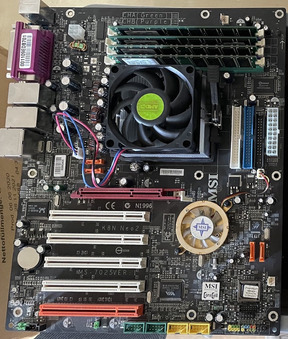
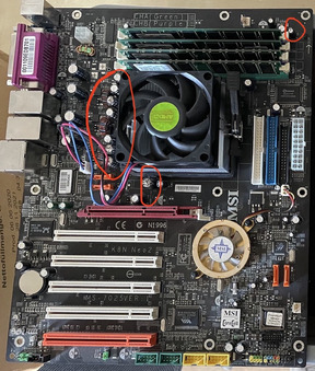
I have a K8N Neo2 (from 2004 ish?) board here that still POSTs, but has visible problems with the capacitors, so I assume I should replace those soon to avoid frying the board and/or CPU?

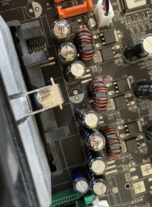
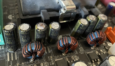
The capacitors near the CPU are labeled as 1800 uF, 6.3 V - it seems like there are 7 of them and 3 show signs of corrosion/leakage(?).

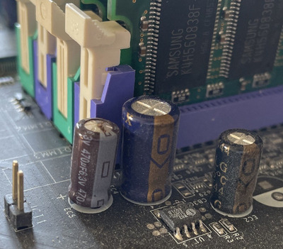
There's another capacitor at the corner of the board (near the RAM sticks) that's labeled as 470 uF, 6.3 V (EC5 printed on the board).

Since I haven't done any capacitor replacement (but read up a bit about it on the 'net), specific questions for this case of some obviously failing capacitors:

  • Are those capacitors near the CPU part of the Voltage Regulator Module (VRM)? Does that mean they affect how stable/clean the power to the CPU is?
  • When replacing those, should I just buy any "1800 uF 6.3 V" (+ 470 uF for the other one) capacitors I can find, or are there other specs that matter?
  • Should I replace just the 3 "broken" ones or all 7, or all similar-specced ones or even ALL caps in that area? Could mismatched (same uF and V value, but different make/model/form factor/age) capacitors lead to problems down the line?
  • Why/how does the board still POST? Are those non-essential/redundant, or are they failing gradually or do they only come into use with certain CPU voltages (say)? Or would these show up as stability issues under load / under high temperatures?
  • Is it possible (and/or useful) to "measure" with a multimeter if the still-good-looking capacitors are failing? Can I measure them while still being soldered into the board, or do I have to desolder, then measure, then either replace or re-solder?

Photos attached of the current state of the board.

Attachments

  • top.jpeg
    Filename
    top.jpeg
    File size
    196.27 KiB
    Views
    460 views
    File comment
    View from the top (capacitors near the CPU)
    File license
    Public domain
  • side.jpeg
    Filename
    side.jpeg
    File size
    149.67 KiB
    Views
    460 views
    File comment
    View from the side (capacitors near the CPU)
    File license
    Public domain
  • corner.jpeg
    Filename
    corner.jpeg
    File size
    204.36 KiB
    Views
    460 views
    File comment
    Leaking capacitor at the corner near the RAM
    File license
    Public domain
  • board.jpeg
    Filename
    board.jpeg
    File size
    309.35 KiB
    Views
    460 views
    File comment
    Board overview without annotations
    File license
    Public domain
  • annotated.jpeg
    Filename
    annotated.jpeg
    File size
    311.3 KiB
    Views
    460 views
    File comment
    Annotated locations of the faulty capacitors
    File license
    Public domain

Reply 1 of 6, by pancakepuppy

User metadata
Rank Newbie
Rank
Newbie
  • Yes, the capacitors next to the toroid inductors are part of the CPU voltage regulator output filtering.
  • You can get into the weeds of component specifications but generally speaking, if a capacitor is 1800 uF and 6.3V it will probably be better than what's in there now. Low ESR and high ripple current rating are also nice for the output filter capacitors of a switching regulator, since it's the job of these capacitors to deal with the triangle-ish shape of inductor current so it doesn't turn into a lot of switching frequency voltage ripple. Also make sure you're getting parts with the right lead spacing and physical dimensions! Having them sit flush on the board and fit next to each other and adjacent parts is always nice.
  • Replace all those capacitors at the same time. If the obviously bad ones are in that condition, I wouldn't expect the ones that aren't split open to be any good either.
  • The regulator can deal with a certain amount of output filter degradation. The performance (voltage ripple/noise, load transient voltage excursions) will get worse but as long as it's not so bad that the CPU glitches, it will boot. You just haven't reached the point of "doesn't work at all" yet.
  • Measuring components in-circuit is tricky, there's a lot of other parasitic stuff going on that can mess with your readings. On top of that, a multimeter may be able to measure capacitance, but there are some aspects of bad capacitors that require an LCR meter (or similar equipment) to check. You should really just replace the not-split open ones anyways.

Reply 2 of 6, by CharlieFoxtrot

User metadata
Rank Member
Rank
Member

When you plan your recap, find datasheets of those original caps and map them on your board and make a list of them. You can't use any general use caps on VRM, originals are very low ESR capacitors with high ripple current capability. Or you can, but results are most likely not good and using incorrect capacitors may cause not only unstable system, but also hardware damage.

For some of these caps equivalent electrolytics may be difficult to find anymore, but you can replace those with polymers and use roughly up to half the capacitance of original capacitors (there are not much over 2000uf polymers available).

Reply 3 of 6, by watson

User metadata
Rank Member
Rank
Member

This is the infamously failure-prone KZJ series from Nippon Chemi-Con (along with KZG). I have attached the datasheet.
As CharlieFoxtrot mentioned, you will probably have to look for polymer capacitors because there are no modern low-ESR replacements that match their specifications.
In fact, the Panasonic FR series (a common choice) does not even come close.

In particular, your 1800uF/6.3 V caps with an 8 mm case size are rated at 12 mΩ ESR and 2350 mA of ripple current at 100 kHz.

Attachments

  • Filename
    KZJ-Series.pdf
    File size
    39.95 KiB
    Downloads
    35 downloads
    File license
    Fair use/fair dealing exception

Reply 4 of 6, by shevalier

User metadata
Rank Member
Rank
Member

in general, everything is visible in the picture.
Its cheap polymer Capxon PS capacitior, and its quite enough.
In those days there were no such loads to look for TDK Epcos industrial capacitors.
file.php?id=159601&mode=view
In the original it was like this
k8n51gmf-63cd1ffee8f43811463559.jpg

Aopen MX3S, PIII-S Tualatin 1133, Radeon 9800Pro@XT BIOS, Diamond monster sound MX300
JetWay K8T8AS, Athlon DH-E6 3000+, Radeon HD2600Pro AGP, Audigy 2 Value

Reply 5 of 6, by thp

User metadata
Rank Member
Rank
Member
CharlieFoxtrot wrote on 2023-09-08, 18:12:

For some of these caps equivalent electrolytics may be difficult to find anymore, but you can replace those with polymers and use roughly up to half the capacitance of original capacitors (there are not much over 2000uf polymers available).

Is there any documentation of how that "roughly up to half" works? Does that mean I'm looking for 1800 / 2 = 900 uF, 6.3V polymer caps? Am I looking for tantalum or aluminium capacitors there?

watson wrote on 2023-09-08, 23:21:
This is the infamously failure-prone KZJ series from Nippon Chemi-Con (along with KZG). I have attached the datasheet. As Charli […]
Show full quote

This is the infamously failure-prone KZJ series from Nippon Chemi-Con (along with KZG). I have attached the datasheet.
As CharlieFoxtrot mentioned, you will probably have to look for polymer capacitors because there are no modern low-ESR replacements that match their specifications.
In fact, the Panasonic FR series (a common choice) does not even come close.

In particular, your 1800uF/6.3 V caps with an 8 mm case size are rated at 12 mΩ ESR and 2350 mA of ripple current at 100 kHz.

Thanks for the data sheet and the values.

I found Panasonic's EEU-FR0J182 with 1800 uF, 6.3 VDC, 1.79 A ripple current and 28 mOhms ESR.
I also found Panasonic's EEU-FC0J182 with 1800 uF, 6.3 VDC, 1.44 A ripple current and 45 mOhms ESR.

I assume I need to match those as closely as possible with 12 mOhms ESR and 2.35 A ripple current?

Does "up to half" the capacitance mean I'm looking for 900 uF, 6.3 VDC, 2.35 A ripple current, 12 mOhms ESR? For ESR I assume lower is better, how about ripple current, is higher better there?

Any brand names / search terms I can use to find fitting polymer capacitors or pointers to guides/tables that I can use? (sorry if I'm missing something obvious)

Reply 6 of 6, by shevalier

User metadata
Rank Member
Rank
Member
thp wrote on 2023-09-11, 15:18:

Does "up to half" the capacitance mean I'm looking for 900 uF, 6.3 VDC, 2.35 A ripple current, 12 mOhms ESR? For ESR I assume lower is better, how about ripple current, is higher better there?

Ripple_Voltage=change of current * ESR.
I.e.
Capacitor have 10mOhm ESR, V_ripple = 50mV
Capacitor have 20mOhm ESR, V_ripple = 100mV = to high noise (ripple) = instability.
ESR should not be higher than the original capacitor.

Capacity refers to the stability of the regulator.
Too small and you'll get oscillations, heat and possibly magic smoke.
In practice, the capacity can be reduced by half (with the same ESR and ripple current) without instability of the entire VRM.

Therefore, the same cheap general use Lelon OCR 1200uF * 4V will be simply ideal.
10 mm diameter, 12 mOhm ESR and 5.5 Ampere ripple current.
http://www.lelon.com.tw/upload/prod/169381783974.pdf

Aopen MX3S, PIII-S Tualatin 1133, Radeon 9800Pro@XT BIOS, Diamond monster sound MX300
JetWay K8T8AS, Athlon DH-E6 3000+, Radeon HD2600Pro AGP, Audigy 2 Value