VOGONS


First post, by janoosh

User metadata
Rank Newbie
Rank
Newbie

Hello, long time lurker and first time poster here, so I hope I am making this thread in correct subforum.

Recently I came into a possession of a (according to warranty stickers) late 90s PC with a quite unusual, in my opinion, combination of CPU and motherboard. It was about to be thrown out (hence the "rescue" in subject), so I thought to myself that I always wanted a machine like this, so I asked the previous owner if I can have it instead. I grew up with a Win 2000/XP machine, only knowing DOS and Windows 9x from old PC mags and old guide books for those OSes; they felt intriguing and mysterious back then and still kinda are, so I was pretty excited when after cleaning it up and checking for blown caps (fortunately none) it actually POSTed. Sorry for long introduction but it might explain a bit why I am invested into getting this guy running as smoothly as possible again.

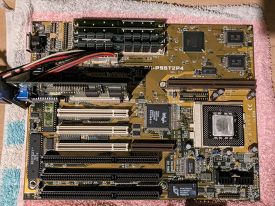
On the surface it looked like a bog standard Socket 7 machine, pretty similar to this LGR build, but when I started disassembling it I noticed some oddities. It has an Asus P/I-P55T2P4 motherboard, revision 2.3, with 256kb of L2 cache soldered on it, a 4MB PowerColor S3 Virge DX, an Aztech SOUND 16B SRS 3D (I think) ISA sound card with AZT2320 chip, a TEAC 3.5 inch floppy drive and NEC 4x CD-ROM drive, and a 200W EMKO PSU (seems to be made in Czech Republic!); so far so good, all of them are in good condition and seem to be working.

Initially I thought it had 64 megs of RAM but POST screen read that it actually has 96, so 2x32 dies and 2x16 dies. There is no TAG SRAM upgrade installed though, and jumper for Memory Cacheable Size was set to 64MB, so it must have been running with a third of its ram uncached. I plan on adding one though as I think I have a compatible one somewhere, if I don't I will just remove 32MB.

Then there's the CPU, it's a Pentium MMX 200MHz (SL27J). To my understanding and according to this thread this particular revision of this mobo does not support MMX processors, yet the board seems to POST just fine. It does seem to have a locked multiplier, as no matter how I set the ratio jumpers it seems to always use 2.5 ratio, so the fastest it can go is 166MHz with a 66MHz bus frequency and slowest is 120MHz with 50MHz bus freq. I don't mind it being limited to 120-166MHz, although what worries me are the voltages. According to underside of the CPU and CPU-World this CPU runs at 2.8 volts, yet the motherboard has only jumpers for STD 3.4V and VRE 3.5V voltages. The jumper is set to STD voltage, and according to whatever previous owner could remember the machine was working fine in that configuration when they still used it all those years ago.

So my question is -- will it be safe to continue using this machine in this CPU configuration? I am planning on using DOS mostly and Windows 95, to play 2D games and generally just have fun with exploring and tinkering with old hardware.

Attached is the picture of the motherboard with S3 installed on my "workbench" (I suffer from chronic lack of empty flat surfaces to work on, this is just temporary), in case someone spots something I missed. Sorry for a long post but I wanted to include as much information as possible. I will answer to any responses tomorrow, as I'm off to bed now, spent too much time tinkering with this tonight.

PXL_20230927_222020496.jpg
Filename
PXL_20230927_222020496.jpg
File size
1.95 MiB
Views
1413 views
File license
Public domain

Reply 1 of 22, by jakethompson1

User metadata
Rank Oldbie
Rank
Oldbie

Indeed the CPU has been over-volted all this time, but it seems many got away with doing that including this board owner. Since it's already been operated out-of-spec for so long, I don't see reason not to keep using it (and keep it well-cooled), and if it dies, downgrade to a plain Pentium.

Is it able to hold the date/time and the other BIOS settings? The battery is inside that Benchmarq chip from 1996 and is long dead by now. If it's socketed, it's relatively easy to replace with a new one (about $15 or so if you buy from a reputable source) or there are ways to hack your old one and attach a new battery to it. You could order one at the same time as you order the tag ram from DigiKey/Mouser...

It's interesting that the codename for Pentium MMX is P55C and this thing is named P55T2P4 but doesn't take P55C CPUs. It must be a concidence.

Reply 2 of 22, by Cosmic

User metadata
Rank Member
Rank
Member

The big heatsink below the CPU socket is a giveaway for a linear voltage regulator. Later boards would have more efficient and smaller switching regulators. Not a big deal, but the former runs hotter so keeping it cool may increase longevity. A CPU sink and a fan in front of the board would also help keep the CPU cool if you'd like to keep running it in its current configuration.

You also have a slot for a COAST module (cache on a stick) above the CPU which may improve performance if supported by the board.

Some ideas for this board: a nice PCI 3D card for early 3D graphics, a PCI USB 2.0 card for file transfers, and an ISA soundcard for good DOS sound support. A PCI IDE card may also improve disk performance.

Reply 3 of 22, by rasz_pl

User metadata
Rank l33t
Rank
l33t
jakethompson1 wrote on 2023-09-28, 00:42:

It's interesting that the codename for Pentium MMX is P55C and this thing is named P55T2P4 but doesn't take P55C CPUs. It must be a concidence.

there is spot for another regulator and jp14-15-16 on rev2 so they were planning full MMX support, but judging by rev3 redesign of whole supply section to switching regulator something went wrong 😀

janoosh did you verify if that 166MHz reading show up on bios screen only or are dos benchmarks also indicating that speed?

Open Source AT&T Globalyst/NCR/FIC 486-GAC-2 proprietary Cache Module reproduction

Reply 4 of 22, by janoosh

User metadata
Rank Newbie
Rank
Newbie

Many thanks to everyone for replies. Sadly, I think something connected to the board or on the board itself kicked the bucket in some way, as it does not POST anymore.

So, as per jakethompson1's suggestion, I was in the process of checking whether the Benchmarq chip was still able to hold BIOS settings, and strangely enough I think it did (at least between reboots in quick succession). I wanted to make sure it was not a fluke, so I powered the machine off and went through the procedure of clearing the RTC RAM, as per manual I found online for this board:

This clears the user-entered information stored in the CMOS RAM of the Real Time Clock such as hard disk information and passwor […]
Show full quote

This clears the user-entered information stored in the CMOS RAM of the Real
Time Clock such as hard disk information and passwords. To clear the RTC
data: (1) Turn off the PC, (2) Short this jumper, (3) Power on the PC, (4) Turn
off the PC, (5) Remove this jumper, (6) Power on the PC, (7) Hold down <De-
lete> during bootup and enter BIOS setup to re-enter user preferences.

And the board didn't POST again after this. I know my keyboard is good as I tested it in a newer machine, and I think my PS/2 to AT adapter is good too as I checked it for continuity between pins, so I think there's no issue with the holding down Delete part. I am getting no video output from the GPU anymore and speaker remains silent, UNLESS I remove all the RAM sticks, then it starts to emit one repeating beep (which as far as I know means RAM issue on Award bios). I tried powering it on with the graphics card in different PCI slots as well, no dice. The PSU is still good as well, I checked the voltages with a multimeter.

Could it mean that the Benchmarq chip was on it's last legs and it just did not have enough juice in it to survive clearing the settings with the jumper, and now the board just refuses to power on at all with it being dead? From what I have read on this forum before, I think this is possible, but I'd like for someone to confirm this suspicion. I was planning on replacing it anyway with one of those open source PCB designs with BQ3285 chips on them, it will take a while for parts to arrive from China though, so I might try doing the mod with attaching a new battery to the dead chip in the mean while, as I have tools and parts for that on hand. I am open to suggestions though, as my practical knowledge with PC hardware is very limited.

@Cosmic, thanks for the suggestions. That was (well, still is, assuming I can get this guy to POST again) my plan for this board. I have a barely used InnoVision Cyber 3DX5000 Voodoo 1 card which I got a long time ago for a good price (just in case I ever got a PC I could install it in 😁) and wanted to use in this machine. Would be a good fit, I think!

@rasz_pl I never got to booting DOS on this thing yet, so the reading was only on POST screen. I will check in DOS though, if I get the chance. Thanks for the tip.

Again, thanks to everyone for replying. I will try hacking the Benchmarq chip over the weekend, hopefully that will get it going again. In the meanwhile I am open to other suggestions.

Edit to add: When I power on the machine, all 3 LEDs on my keyboard briefly flash. Not sure if this is part of a keyboard self-test or motherboard doing something, but it might be an important clue.

Reply 5 of 22, by PcBytes

User metadata
Rank Oldbie
Rank
Oldbie

Just replace the Benchmarq. I know that a handful if not most of the boards of that era don't like if the RTC chip is missing.

"Enter at your own peril, past the bolted door..."
Main PC: i5 3470, GB B75M-D3H, 16GB RAM, 2x1TB
98SE : P3 650, Soyo SY-6BA+IV, 384MB RAM, 80GB

Reply 6 of 22, by rasz_pl

User metadata
Rank l33t
Rank
l33t

Im a big proponent of reuse, why throw perfectly fine chip just because battery died when you can go medieval on it with a file/exacto knife/soldering iron
https://www.youtube.com/watch?v=svPNxILeQEw
https://imgur.com/gallery/N5GEx

Open Source AT&T Globalyst/NCR/FIC 486-GAC-2 proprietary Cache Module reproduction

Reply 7 of 22, by rmay635703

User metadata
Rank Oldbie
Rank
Oldbie

Single rail motherboards can be modified for lower voltages.

2.8-3.1 volts is possible but some boards can become unstable if you go too low since the chipset and ram touches it also.

Modifying your motherboard's voltage regulator for overclocking

Last edited by rmay635703 on 2023-10-04, 19:30. Edited 1 time in total.

Reply 8 of 22, by janoosh

User metadata
Rank Newbie
Rank
Newbie

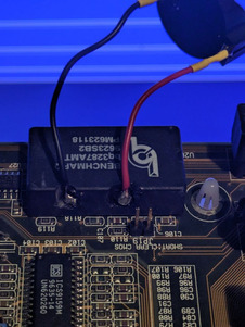
Well, I said I'd get to it over weekend but life got in a way. I just did the RTC mod and this mobo POSTs again 😁 Was a bit stressful though, as not only I did the mod without desoldering the module first (figured I might desolder it when sockets arrive, no point in doing it twice, also seen people do it this way on this forum before), I also never really used Dremel type tools before in such precise way in a delicate environment like this. Fortunately the resin (or whatever this material is) covering these modules is really soft so it was fairly easy to do on low speed setting. The solder did not want to stick to uncovered bits at all, that's why there's quite a bit of it in there, so excuse my workmanship. Also, after I soldered the battery holder on I remembered that I did not cut off the internal dead battery, and I did not want to go through soldering the leads to this module again, so it's still connected... Hopefully this won't cause any problems at least before parts for replacement arrive. For what it's worth, the dead internal battery measured 2.8 volts.

@rasz_pl – I am actually going to build the same module you linked to. After some research I decided that Necroware's design is easiest to obtain parts for and build. It's also well documented IMO.

@rmay635703 – Interesting, do you have any resources to share about such mod? As I couldn't find any myself. I'm wondering if it's worth to attempt such mod, probably easier to just get a non-MMX Pentium though for this particular board.

To wrap this up – I am so happy I got this machine to run again. Now I'm going to finish cleaning the case it came in, get DOS running as well, see how it reacts to the MMX and what not, replace PSU and CPU fans as they are very much on their last legs, maybe test if my Voodoo works too. I will make sure to share the entire build when it's finished, in the configuration it came with. Then hopefully the parts and other stuff I want to use with it will start arriving, so I will be able to share the riced out version 😁 Thanks to everyone for help and contribution.

Edit: Forgot to attach the picture, think I did pretty good for a first timer.

Attachments

Reply 9 of 22, by rmay635703

User metadata
Rank Oldbie
Rank
Oldbie

You need to identify the specific linear regulator and since your board likely already has 2 voltage settings VR and VRE you could just sacrifice one of the unused settings by (normally) changing the resistor values to target your desired voltage .

Removing the cpu and using a multimeter is sometimes necessary to fine tune if you can’t find the spec sheet for your part.

Reply 10 of 22, by rasz_pl

User metadata
Rank l33t
Rank
l33t

Asus P/I-P55T2P4 2.x has provisions for 2 voltage rails, so IMO there is quite easy road to a proper MMX/K6 mod.
Vcore is:
U24 LP2951ACM linear regulator
U25 screwed to the radiator, PNP D45H2A?

Spots for missing VIO rail:
U21 missing, guessing another D45H2A working in tandem with U22?
U22 LP2951ACM
U23 missing, wtf would that be? there is spot for radiator but I cant figure where and what is the pinout?
L6 maybe provision for a coil, but why when we got spot for two linear regulators?
Q1 Q3 A4 maybe potential discrete smps controller?

My guess is they designed dual linear regs, then ran some tests and it was cooking so abandoned support for dual rail until 3.x series.

2.1 looks same as 2.0? https://hsdl-blog-jp.translate.goog/archives/ … &_x_tr_pto=wapp
3.0 version is half SMPS half linear, U26 is linear regulator lt1084, BYV118 schottky diode and two NDP6030?
3.1 version implements proper dual SMPS converter. NDP6030 N-channel mosfets paired with some unidentified diodes. I dont see controller, only LM357 opamp and some transistors so its all discrete.

Open Source AT&T Globalyst/NCR/FIC 486-GAC-2 proprietary Cache Module reproduction

Reply 11 of 22, by janoosh

User metadata
Rank Newbie
Rank
Newbie

Thanks for some interesting pointers to you both. Seems it is doable, in theory at least. For now it also seems that it's still above my pay grade, and I don't want to risk ruining an otherwise perfectly fine board. Might come back to this idea though when I feel more confident in my skills.

Reply 15 of 22, by janoosh

User metadata
Rank Newbie
Rank
Newbie

Yup, it's missing. Fortunately it was removed in non-destructive way. I considered all my other options on how to boot it. I don't have an IDE HDD small enough to work without a modified BIOS; manual says this board supports booting from CDs so I could try flash it that way, but I'd probably go through quite a few of them before I got one with all software I need to flash it. Figured that it's not worth the hassle, but if the SD to IDE adapter does not arrive before weekend I might as well attempt to do so.

Reply 17 of 22, by janoosh

User metadata
Rank Newbie
Rank
Newbie

Oooh, I did not know that, that's great. Thought it'd just refuse to work with a bigger HDD at all 😅 Well then, I'll try booting from a CD tomorrow, hopefully the drive still works and the board does indeed support booting from it. Thanks for correcting my long-time misunderstanding!

I have an Asus USB/MIR board for this machine as well, so hopefully when I get an OS with USB support installed it will be smooth sailing (as smooth as USB 1.x speeds allow, at least) in terms of getting files to and from this machine.

Reply 18 of 22, by janoosh

User metadata
Rank Newbie
Rank
Newbie

Took me a couple of days but finally I can post some kind of update and also a success story! I suppose I will use this thread to document my build now.

So following jakethompson1's advice, I plugged in a random IDE HDD I had laying around, grabbed my Windows 98 OEM CD, connected both HDD and CD-ROM drive to the motherboard, put in the CD, set correct boot order in bios, restarted the machine, and it booted just fine! Well, that is until I selected "boot from CD" in the Win98 CD boot menu. PC seemed to freeze, CD drive stopped all activity, and monitor only displayed the blinking prompt character. No big deal, maybe my Win98 CD is just too old. I burned a legacy FreeDOS 1.3 CD to test the drive with a known working disc, it also only booted partway, dropped me to FreeDOS shell after trying to set up the CD drive... Cue couple of hours of research how booting from CD worked back then, all that El Torito stuff, figured my drive was old enough that it did not really work well with those kinds of CDs. I found couple other IDE CD drives in my parts, unfortunately both seemed to be dead.

So I decided I'd try one last thing. I found a box of floppies in the meantime, from back when my family PC still had a floppy drive. My plan was to burn a Windows 98 boot floppy image to a CD, boot it and copy it's contents to a formatted floppy, then boot from that and access the setup CD that way. Before that I had to find an empty and working floppy though. So I grabbed the first one from the stack, an unlabelled Verbatim, put it in my floppy drive, and just for fun turned on the machine to see if, by some chance, it boots to something. "Starting Windows 95...". It was a Windows 95 boot floppy... Which I must have burned as a kid like 15 or so years ago, for reasons now lost to time. I was so happy to see this message, seems like my life-long interest in old computers and a tendency to never throw away obsolete media paid off in a bizarre way. For fun I checked other floppies, one booted to Windows 1 point something, and another was a My Super MS-DOS boot disk from China DOS Union.

Smooth sailing from then, launched Windows 98 setup using the 95 boot floppy, in the setup I created a Windows 98 floppy to have a backup, installed 98, installed USB mass storage drivers I had burned on a different CD previously, everything worked fine. One drive died on me during this process (newest one from 2007), another was doing something funny to the PSU power lines I think as with it connected CD drive refused to spin up, third and oldest one still works perfectly fine. I updated the BIOS to the patched version with no issues as well. Interestingly, with patched BIOS the initial memory test is so fast that I have barely any time to look at and admire POST screen now. Weird complaint to have, I know.

In the meantime I also swapped fans both on the CPU cooler and in the PSU. Funny thing is, I noticed that this particular PSU turns itself off when it detects no or low load, and apparently new fan is so efficient with power usage that PSU thinks there's no load and turns itself off. Thought I killed it until I plugged my motherboard to it. For reference, I used AAB Super Silent series fans, as I've seen them recommended here in Poland as a cheap and decent option for refreshing these old PSUs and PCs. I also thoroughly cleaned the case and remove rust from the chassis. Disassembled both CD and floppy drives to apply some fresh lube on the gears and add some machine oil to the threaded bars. CD drive now boots CDs with no problem at all after this process, I wonder if that's cause of updated BIOS or fresh lubrication 🤔

As for upgrades, I've added a TAG SRAM, it's a Winbond chip, funny thing is it was the cheapest part of the entire build as it cost me just over 1 USD on a local auction site. I've also tested my IDE to SD adapter, which also works just fine, I'm in the process of modifying BFeely's 5.25 inch enclosure design to fit into a 3.5 inch bay. I also wanted to install a Lian Li 5.25 inch HDD caddy thing I had laying around, sadly it seems it's IDE ribbon is broken cause PC does not detect any drive plugged into it. Shame cause it's black, and it'd break the monotony of off-white, beige front of the case. Plugged in my Voodoo 1 as well, didn't test it with any games yet but it passes through graphics from the GPU fine so I hope the 3D part of it works fine as well. I've also got a Dreamblaster S2 for the Aztech sound card, as it's onboard MIDI synth is charming, charmingly bad in fact. Just as I remember them from back in the day 😅 It's a great little upgrade for a budget build like mine. Also installed a random Windows 9x compatible PCI network card I found in my parts, will be far easier to just use FTP or something to transfer files instead of plugging a USB drive between my machines.

In the meantime the RTC died on me as well. Turns out one of the leads to the battery holder broke off. Tried to fix it, couldn't solder it back no matter what temperature I used, how much flux I added, so I gave up on it. Fortunately parts for a replacement arrived so you can see it installed on the bottom of the board as well. Desoldering the old one from the board was a major PITA though, added a DIP socket to avoid having to do it again in future.

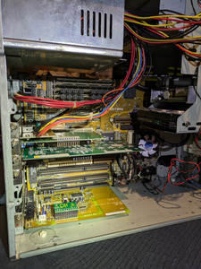
So that's where I'm at now. Attached is the picture of this PC in it's current state. It actually took me like 3 hours to put it together, as this case is without any doubt the worst case I had worked with. Sharp edges I expected, but how it fits (or rather doesn't...) is just terrible. Motherboard has to sit at an angle connected to only one standoff so the expansion card slots line up with back of the case, with both standoffs screwed in only two of the cards it came with lined up. I had to check photos I took during initial disassembly to see if I'm doing something wrong, I compared it with random pictures of this particular case I found online to see if I'm not going crazy, and no I'm not, it's just a terrible case. Not to mention it's very cramped as well. Terrible stuff. A keen eye might notice that sound card is not fully inserted into it's slot, but it just doesn't go in any further than that. Everything in this case is just slightly misaligned like that.

So couple of questions to finish this long post off:
1. I still have one PCI and one ISA slots available (2x ISA if I don't use that PCI). Are there any expansion cards which would compliment this already weird build well? I was thinking about getting a USB 2.0 card to speed up file transfers, as someone earlier in this thread suggested, but if I get network going I don't think I will need one.
2. I'm thinking about getting an L2 cache upgrade as well. From what I know, upgrading from 256k to 512k should not really be a noticeable improvement, so mostly I want to do it just for fun. The manual for this board says the following:
>WARNING: If the cache module that you install already have an extended tag, do
>not install another TAG SRAM into the TAG SRAM Upgrade Socket.
Is there a way to tell if a cache module has an extended TAG on it? On local auction sites I can find a couple of these modules, but at most they are described as 256k cache module, so no details about TAG. Don't want to buy one blindly and accidentally damage my board that way, if it's even possible.

I also have one 5.25 inch bay free, but I think I can figure something interesting to put in there myself. Sorry for a long post, I had to gather my thoughts about this whole process somewhere.

Edit: Forgot to attach the photo. Any spots on the case you see and might think are rust spots are just shiny steel reflecting furniture in my room 😅
Attachments

Reply 19 of 22, by Repo Man11

User metadata
Rank Oldbie
Rank
Oldbie

I'm curious to know if the USB ports on this board are fully functional? I know they work with the later revisions that supported dual plane voltage CPUs.

"I'd rather be rich than stupid" - Jack Handey