VOGONS


First post, by gmipf

User metadata
Rank Newbie
Rank
Newbie

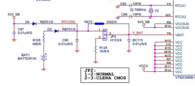
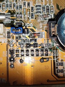
My motherboard is a Gigabyte GA-6VXE7+ (rev. 1.0). Without a battery installed the motherboard starts and posts, I can enter bios etc. Everything seems fine. With a battery installed the motherboard doesn't react at all, no fan spin, nothing. The pwr header still has 5v but shorting does nothing. I need to remove the battery, turn off the psu, wait until the voltage on the pwr header drops to 0V. After that the motherboards starts again without a battery. To me it seems like a short somewhere when the battery is installed. I also have removed the battery holder and found some battery leakage which I have cleaned up, the traces below seemed ok to me there. My other theory is the diode which connects to the battery 3v line. The place where the rtc and cmos ram is located seems to be the southbridge VIA VT82C596B. I don't know how to go further, any ideas?

Last edited by gmipf on 2023-10-13, 23:38. Edited 1 time in total.

Reply 3 of 7, by gmipf

User metadata
Rank Newbie
Rank
Newbie

I have attached a photo of my diodes. I think D19 and D21 corresponds to the diodes D4(D21) and D5(D19) of your schematic, both are connecting to the left header. I have removed both, the measurements are as follows:

D19: 0,34v | backwards: 0L
D21: 0,264v | backwards: 0,292v

I'm not an electronics expert and never measured diodes before but I would assume D21 is defective right?

Attachments

  • diodes.jpg
    Filename
    diodes.jpg
    File size
    351.47 KiB
    Views
    482 views
    File license
    Public domain

Reply 5 of 7, by gmipf

User metadata
Rank Newbie
Rank
Newbie

Thank you very much. I have measured more diodes unrelated to the battery on the same board. Without removing them some more seem to be suspicious. How do I identify diodes without a schematic?

Are those rb751 all correct? https://www.digikey.de/de/products/base-produ … 88/RB751/143052

Some has 30mA and some 1mA ratings. I wanted to order this pack, which is cheapest for me: https://www.ebay.de/itm/266402100359
But the rating is 200mA.

EDIT: OK I think I got it, it is the max current the diode is able to handle. Therefore most of them should be OK I think.

EDIT2: Could you share the the full schematic from where you cropped the picture off? Maybe it could be useful for more. Thanks.

Reply 7 of 7, by gmipf

User metadata
Rank Newbie
Rank
Newbie

The diodes have arrived and the board is working now! 😁 Thank you again for your efforts.

Attachments

  • diodes_new.jpg
    Filename
    diodes_new.jpg
    File size
    492.25 KiB
    Views
    347 views
    File license
    Public domain