First post, by epictronics

Rank
Newbie
- Rank
- Newbie
Hi,
If I'm not mistaken, it's possible to hack a 128k sidecar to take 512k.
Does anyone here know where I can find the instructions?
Thanks!
Hi,
If I'm not mistaken, it's possible to hack a 128k sidecar to take 512k.
Does anyone here know where I can find the instructions?
Thanks!
Lost the site I was thinking of, but found this one, don't know if it gets you any closer... https://www.brutman.com/PCjr/pcjr_mods.html
Unicorn herding operations are proceeding, but all the totes of hens teeth and barrels of rocking horse poop give them plenty of hiding spots.
Brutman.com has forum you can ask on or I might have the links to some old PCJr newetters that I think have the instructions.
Memory serves me the IBM takes more modification then just replacing the chips, the Tecmar Jr Captains I have just require replacing the chips and that's it.
BitWrangler wrote on 2023-10-09, 17:04:Lost the site I was thinking of, but found this one, don't know if it gets you any closer... https://www.brutman.com/PCjr/pcjr_mods.html
Thanks, that's how far I got.
It doesn't say if It can be done with my original IBM sidecar. I hope it does!
Grem Five wrote on 2023-10-09, 19:16:Brutman.com has forum you can ask on or I might have the links to some old PCJr newetters that I think have the instructions.
Memory serves me the IBM takes more modification then just replacing the chips, the Tecmar Jr Captains I have just require replacing the chips and that's it.
Thanks, I have requested a login to the forum.
If you are there you should check the thread on PC sprint/PCJr sprint and see the clock speeds others have gotten.
So far all I have been able to find is this from - PCJr Power by Albert L. Allen * copyright 1989 *
IBM 128K MEMORY SIDECAR UPGRADE TO 512K If you have a PCjr with a attached 128K memory sidecar you can upgrade that sidecar to h […]
IBM 128K MEMORY SIDECAR UPGRADE TO 512K
If you have a PCjr with a attached 128K memory sidecar you can upgrade that sidecar to house a full 512K of memory. Bringing your junior to full 640K.
WARNING: This modification is for people who are experienced in soldering and unsoldering on printed circuit boards.
PARTS NEEDED16 256K DRAM BY 150 ns (see handling and type page)
16 Good 16 pin low profile sockets
7" #28 or #30 tinned copper wire
TOOLS NEEDED1 Small. good quality diagonal cutters
1 Low wattage soldering iron
1 Desoldering tool (Solder Sucker) and some solder wick
1 Small Screwdriver
1 Small pliers or hemostats
1 Soldering tool
1 Old toothbrush for cleaning
1 X-acto knife
Solder Fine. rosin coreGETTING STARTED
Shut off power to your junior and remove the 128K sidecar. Completely remove the four mounting screws. Separate the sidecar halves at the pry points with a small screwdriver. There are eight catches holding the halves together, 4 top and 4 bottom. Remove the circuit board and lay it on a clean work area with plenty of light.
There appears to be three different versions of the IBM PCjr Memory sidecars. Two versions require no additional work but the third version requires you to cut one wire and solder in a extra wire.
VERSION 1 - looks very messy. There are many green wires covering the card. These wires are not the green traces that are part of the board but are extra wires that were added after the board was made. No extra work required.
VERSION 2 - looks neat. No extra wires and one of the positions for a chip was left empty. No extra work required.
VERSION 3 - looks clean. There is one green wire connecting pin 1 of the 64K chip to one of the resistor packs (the long, skinny yellow colored device with many pins in one row). There is also a position where a chip could go that is
empty. You will note one of the board traces has been cut. This board requires extra work. (see diagram) Remove this green wire completely by cutting it from the board with the diagonal cutters.Using you small diagonal cutters completely cut all of the legs of the installed 64K DRAM chips. Do not attempt to save the 64K chips. Cut the legs closest to the chip, NOT to the board.
With a pair of needle nose pliers and your soldering iron, remove each cut leg from the board. Apply the heat from the soldering iron at the component side. Grip the leg to be removed with the pliers and remove each leg.
Remove all of the solder from the holes with soldering iron and desoldering tool (solder sucker). Some holes may require the use of the solder wick to draw up this solder.
Scan the board and cleaned holes for excess solder, loose chip legs or anything that is not apart of the board. Clean the board with a solder tool and brush the board with the toothbrush to be sure that you have cleaned it thoroughly. THIS IS MOST IMPORTANT as solder shorts become extremely hard to find once the sockets are installed.
Install the board back onto the side of the junior without its case, and turn the unit on. The power on self test (POST) should count to 128K as normal. Shut the unit off and remove the sidecar board and continue with the modification.
Orient the 16 sockets into the cleaned holes and solder them into the board.
If your card had the one green wire on it, add this extra step now. The trace that connects pin 1 of DRAM 1-2 to the 7th pin from the left of the second horizontal resistor pack from the left has been cut.(see diagram) You must reattach the two sides of this trace. Cut a length of the wire and insert it into the hole for pin 1 of DRAM 1-2 before you insert the socket and solder them both in at the same time. Run the other end to the 7th pin from the left of the second resistor pack from the left. You may place this wire on the component or trace side of the board.
With the component side of the board up (facing you) locate the set of three plated through holes to the right of the large chip (74S409 DRAM Controller) with a white rectangle drawn around them. This is a jumper which determines whether 64K or 256K chips are used. At present there is a foil trace on the component side which connects the left and center holes together. Completely cut this foil trace which connects the two holes with a X-acto knife. Then solder a jumper wire between the center hole and the right hole. See the diagram to locate this section.
FINISHING UPSet all four DIP switches on the rear of the board to their "OPEN" position (on). It is advisable to place a piece of electrical tape over the 8 pin positions on the bottom of the board below the DIP switches to keep them from shorting to the case.
Carefully install the 16-256K chips into their sockets. Be sure each chip is oriented properly. Pin 1 pointing downward, just as the 64K chips you removed. (See section for handling and installing 256K chips)
Attach the sidecar board to the junior and turn the power on. Make sure the POST now counts to 640K before the drive light is activated.
Reinstall the modified sidecar board into its case, and back onto the PCjr.
Again, turn the PCjr on and verify the POST to 640K with no errors. You must use the IBM Memory Options diskette to configure the DOS diskette to recognize your memory. If your DOS was already configured to recognize 256K it will automatically see the full 640K. Use CHKDSK to confirm you full memory capabilities.
DEBUGGING
If something doesn't work, our experience indicates that almost all of the problems are with soldering. Make sure no shorts were caused by your soldering.
If nothing happens when you test the finished board, check for a solder bridge shorting the power supply. One or more of the 256K chips could be installed backward. These chips will auto-destruct if power is applied to them when they are in wrong.
If the POST doesn't see any memory above 128K, one of the 256K chips is bad, or some of the pins on one or more of these chips is bent. If the switches are not properly set the adapter can act like this also,
If the POST counts past 128K but stops at a 128K boundary you should check the switches.
If the POST counts past 128K but not all of the way to 640K you probably have a bad 256K chip. Also check the jumper for a complete cut through or proper soldering on the jumper that you added.
If you get a "ERROR A" you probably have a bad 256K chip.
To get full compatibility, you'll need to finish missing items that PCjr were missing with. DMA is one of these.
Cheers,
Great Northern aka Canada.
Pile of Junior mods here, 640k mod near the top, bit hard to read..
http://etc.pixesthesia.com/jrstuff/
Still haven't found that site where the dude had a load of new old stock PC Jr stuff for sale also, thought he had mods and guides.
Unicorn herding operations are proceeding, but all the totes of hens teeth and barrels of rocking horse poop give them plenty of hiding spots.
Grem Five wrote on 2023-10-09, 21:48:So far all I have been able to find is this from - PCJr Power by Albert L. Allen * copyright 1989 *
IBM 128K MEMORY SIDECAR UPGRADE TO 512K If you have a PCjr with a attached 128K memory sidecar you can upgrade that sidecar to h […]
IBM 128K MEMORY SIDECAR UPGRADE TO 512K
If you have a PCjr with a attached 128K memory sidecar you can upgrade that sidecar to house a full 512K of memory. Bringing your junior to full 640K.
WARNING: This modification is for people who are experienced in soldering and unsoldering on printed circuit boards.
PARTS NEEDED16 256K DRAM BY 150 ns (see handling and type page)
16 Good 16 pin low profile sockets
7" #28 or #30 tinned copper wire
TOOLS NEEDED1 Small. good quality diagonal cutters
1 Low wattage soldering iron
1 Desoldering tool (Solder Sucker) and some solder wick
1 Small Screwdriver
1 Small pliers or hemostats
1 Soldering tool
1 Old toothbrush for cleaning
1 X-acto knife
Solder Fine. rosin coreGETTING STARTED
Shut off power to your junior and remove the 128K sidecar. Completely remove the four mounting screws. Separate the sidecar halves at the pry points with a small screwdriver. There are eight catches holding the halves together, 4 top and 4 bottom. Remove the circuit board and lay it on a clean work area with plenty of light.
There appears to be three different versions of the IBM PCjr Memory sidecars. Two versions require no additional work but the third version requires you to cut one wire and solder in a extra wire.
VERSION 1 - looks very messy. There are many green wires covering the card. These wires are not the green traces that are part of the board but are extra wires that were added after the board was made. No extra work required.
VERSION 2 - looks neat. No extra wires and one of the positions for a chip was left empty. No extra work required.
VERSION 3 - looks clean. There is one green wire connecting pin 1 of the 64K chip to one of the resistor packs (the long, skinny yellow colored device with many pins in one row). There is also a position where a chip could go that is
empty. You will note one of the board traces has been cut. This board requires extra work. (see diagram) Remove this green wire completely by cutting it from the board with the diagonal cutters.Using you small diagonal cutters completely cut all of the legs of the installed 64K DRAM chips. Do not attempt to save the 64K chips. Cut the legs closest to the chip, NOT to the board.
With a pair of needle nose pliers and your soldering iron, remove each cut leg from the board. Apply the heat from the soldering iron at the component side. Grip the leg to be removed with the pliers and remove each leg.
Remove all of the solder from the holes with soldering iron and desoldering tool (solder sucker). Some holes may require the use of the solder wick to draw up this solder.
Scan the board and cleaned holes for excess solder, loose chip legs or anything that is not apart of the board. Clean the board with a solder tool and brush the board with the toothbrush to be sure that you have cleaned it thoroughly. THIS IS MOST IMPORTANT as solder shorts become extremely hard to find once the sockets are installed.
Install the board back onto the side of the junior without its case, and turn the unit on. The power on self test (POST) should count to 128K as normal. Shut the unit off and remove the sidecar board and continue with the modification.
Orient the 16 sockets into the cleaned holes and solder them into the board.
If your card had the one green wire on it, add this extra step now. The trace that connects pin 1 of DRAM 1-2 to the 7th pin from the left of the second horizontal resistor pack from the left has been cut.(see diagram) You must reattach the two sides of this trace. Cut a length of the wire and insert it into the hole for pin 1 of DRAM 1-2 before you insert the socket and solder them both in at the same time. Run the other end to the 7th pin from the left of the second resistor pack from the left. You may place this wire on the component or trace side of the board.
With the component side of the board up (facing you) locate the set of three plated through holes to the right of the large chip (74S409 DRAM Controller) with a white rectangle drawn around them. This is a jumper which determines whether 64K or 256K chips are used. At present there is a foil trace on the component side which connects the left and center holes together. Completely cut this foil trace which connects the two holes with a X-acto knife. Then solder a jumper wire between the center hole and the right hole. See the diagram to locate this section.
FINISHING UPSet all four DIP switches on the rear of the board to their "OPEN" position (on). It is advisable to place a piece of electrical tape over the 8 pin positions on the bottom of the board below the DIP switches to keep them from shorting to the case.
Carefully install the 16-256K chips into their sockets. Be sure each chip is oriented properly. Pin 1 pointing downward, just as the 64K chips you removed. (See section for handling and installing 256K chips)
Attach the sidecar board to the junior and turn the power on. Make sure the POST now counts to 640K before the drive light is activated.
Reinstall the modified sidecar board into its case, and back onto the PCjr.
Again, turn the PCjr on and verify the POST to 640K with no errors. You must use the IBM Memory Options diskette to configure the DOS diskette to recognize your memory. If your DOS was already configured to recognize 256K it will automatically see the full 640K. Use CHKDSK to confirm you full memory capabilities.
DEBUGGING
If something doesn't work, our experience indicates that almost all of the problems are with soldering. Make sure no shorts were caused by your soldering.
If nothing happens when you test the finished board, check for a solder bridge shorting the power supply. One or more of the 256K chips could be installed backward. These chips will auto-destruct if power is applied to them when they are in wrong.
If the POST doesn't see any memory above 128K, one of the 256K chips is bad, or some of the pins on one or more of these chips is bent. If the switches are not properly set the adapter can act like this also,
If the POST counts past 128K but stops at a 128K boundary you should check the switches.
If the POST counts past 128K but not all of the way to 640K you probably have a bad 256K chip. Also check the jumper for a complete cut through or proper soldering on the jumper that you added.
If you get a "ERROR A" you probably have a bad 256K chip.
Thanks!
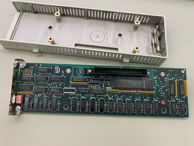
It seems I have the version 2 cart but I have a different RAM controller on my board. (dp8409an) instead of the 74S409.
I'll try this mod when I get the Skinny-Sprint V2 boards.
Faster RAM chips are already on the way to replace the onboard RAM. Hopefully, they were preventing the jr from going past 8.2MHz.
BitWrangler wrote on 2023-10-10, 02:05:Pile of Junior mods here, 640k mod near the top, bit hard to read..
http://etc.pixesthesia.com/jrstuff/Still haven't found that site where the dude had a load of new old stock PC Jr stuff for sale also, thought he had mods and guides.
Great resource, thanks!
pentiumspeed wrote on 2023-10-09, 22:58:To get full compatibility, you'll need to finish missing items that PCjr were missing with. DMA is one of these.
Cheers,
Yeah, the PCjr is quite a quirky machine for sure. But that's why I find it fun and interesting