VOGONS


First post, by boby

User metadata
Rank Member
Rank
Member

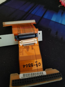
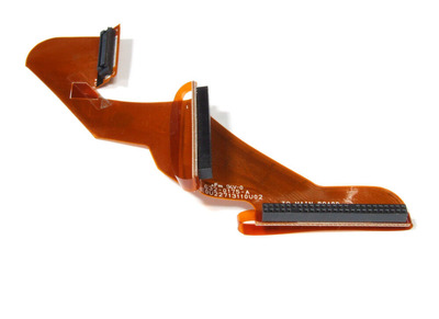
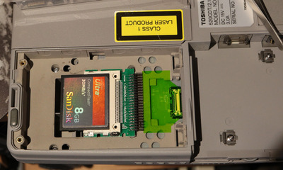
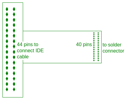
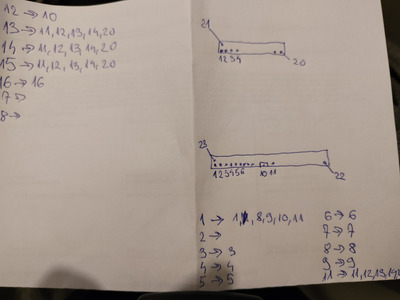
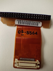
Hi, I am looking for this cable everywhere but simply can't find it. Another problem is I don't know how to search for it as I don't know the name of the connector.
Please check the attachment.

Thank you!

Attachments

Last edited by boby on 2024-01-18, 08:46. Edited 2 times in total.

Reply 1 of 19, by gmipf

User metadata
Rank Newbie
Rank
Newbie

Here was a seller once: https://www.aliexpress.com/i/1995347755.html

EDIT: And here: http://www.cmyhub.com/proinfo/Toshiba-Tecra-5 … able_10020.aspx

EDIT2: It seems the partno is "FALHD1". Here is a page where you can ask stock: https://www.tamayatech.com/parts.php?g=FALHD1

Reply 2 of 19, by Thermalwrong

User metadata
Rank Oldbie
Rank
Oldbie

They have no stock, but the part codes may help for finding in other places: https://www.impactcomputers.com/p000245460.html?cpidx=149371
That's just a regular JAE connector, I wonder what it'd take to make a reproduction but cheaper - using 2x PCBs and a generic 44/50 pin flat cable.

Reply 3 of 19, by boby

User metadata
Rank Member
Rank
Member

Wow guys, thx much!
@Thermalwrong, do you think it's doable? I have some soldering skills and soldering iron, but never did something this tiny and I have no microscope 🙂

EDIT1: Unfortunately all this links don't have it in stock. I was not able to find it using the numbers provided either. 🙁

EDIT2: I know I am asking too much, but can somebody with better searching skills find this thing somewhere, where it can be bought. I'll buy you a beer 🙂 🍺

EDIT3: I found this on ebay (2nd image), but not sure if that is the connector I need, because I have similar cable and it's connector is bigger then the one I need (1st image)

Attachments

  • IMG20231013095329.jpg
    Filename
    IMG20231013095329.jpg
    File size
    49.52 KiB
    Views
    1011 views
    File license
    Public domain
  • s-l1600.jpg
    Filename
    s-l1600.jpg
    File size
    44.41 KiB
    Views
    1011 views
    File license
    Public domain

Reply 4 of 19, by Thermalwrong

User metadata
Rank Oldbie
Rank
Oldbie
boby wrote on 2023-10-12, 12:13:
Wow guys, thx much! @Thermalwrong, do you think it's doable? I have some soldering skills and soldering iron, but never did some […]
Show full quote

Wow guys, thx much!
@Thermalwrong, do you think it's doable? I have some soldering skills and soldering iron, but never did something this tiny and I have no microscope 🙂

EDIT1: Unfortunately all this links don't have it in stock. I was not able to find it using the numbers provided either. 🙁

EDIT2: I know I am asking too much, but can somebody with better searching skills find this thing somewhere, where it can be bought. I'll buy you a beer 🙂 🍺

EDIT3: I found this on ebay (2nd image), but not sure if that is the connector I need, because I have similar cable and it's connector is bigger then the one I need (1st image)

I've hunted down a few of these pesky board to board connectors before, it's a real rabbit hole. I pulled out my Toshiba Tecra 520CDT which uses the same cable and measuring the connector and looking at the pin pitch, I think this is a suitable replacement: https://www.mouser.co.uk/ProductDetail/Phoeni … LtWYTNbug%3D%3D
Possibly not identical to the original and black instead of white, but the dimensions all check out and the keying looks exactly the same.
Much too small to solder any of it by hand in my opinion.

In regards to getting this working I think now that I'm looking at the 520CDT and how the connector fits; a simple PCB could be made that goes from that board-to-board connector and breaks it out to a 44-pin 2mm pitch connector. However the cheap and easy way to do this will not allow for use of a regular hard drive, only compactflash / IDE-to-mSATA adapters since the angles that the flex cable achieves would cost a lot, but a flat PCB with a connector on one side and the 44-pin on the end should be cheap to make

Sadly, the Tecra 520 to 550 models are an area where we don't have the detailed maintenance manual, so it's going to be necessary to figure out the whole pinout first.

Attachments

Reply 5 of 19, by boby

User metadata
Rank Member
Rank
Member

In regards to getting this working I think now that I'm looking at the 520CDT and how the connector fits; a simple PCB could be made that goes from that board-to-board connector and breaks it out to a 44-pin 2mm pitch connector. However the cheap and easy way to do this will not allow for use of a regular hard drive, only compactflash / IDE-to-mSATA adapters since the angles that the flex cable achieves would cost a lot, but a flat PCB with a connector on one side and the 44-pin on the end should be cheap to make

Not sure that I understood this part correctly. Why one couldn't break this board and solder a regular 44 pins IDE connector with some short cable to it? Then you have it kind of flexible to connect hard drive.
Second thing I don't get is, do you have this board already or what is shown on your photo? And how exactly to make it, when the connector on the motherboard is small as well for hand soldering?

Reply 6 of 19, by Thermalwrong

User metadata
Rank Oldbie
Rank
Oldbie

It's an idea only at the moment, steps to make this:
1. Work out the pinout for the 40-pin connector by checking against the known 44-pin connector's pinout with a multimeter
2. Design up a small 2-layer PCB in KiCAD, which requires making these parts for the component library and a schematic based on the 40pin + 44pin connectors joining them together
3. Get PCBs fabricated by one of the cheap PCB makers like JLC or PCBway
4. Get the connectors from Mouser (I'm doing a big order with them quite so I'll get some of these connectors to check fit) or someplace else
5. Solder the board together, then test

While a 44-pin cable could work, there's still not enough physical space to fit a cable with the regular size 2.5" hard drive installed. It only fits as it does because flex PCBs enable that all to fit in that tiny space with those angles - but flex PCBs are very expensive for hobby projects, like a simple hard PCB would is less than 10$ for 5 boards, I'm pretty sure flex PCB is 10x that and only makes sense in big quantities.

Reply 7 of 19, by DerBaum

User metadata
Rank Oldbie
Rank
Oldbie
boby wrote on 2023-10-12, 12:13:

EDIT3: I found this on ebay (2nd image), but not sure if that is the connector I need, because I have similar cable and it's connector is bigger then the one I need (1st image)

This looks like a cable to connect a HDD and a CD rom to the mainboard (the connector towards the camera says "to mainboard"... so the weirdo connector is probably for a cd rom drive.

FCKGW-RHQQ2

Reply 8 of 19, by boby

User metadata
Rank Member
Rank
Member
DerBaum wrote on 2023-10-13, 21:04:
boby wrote on 2023-10-12, 12:13:

EDIT3: I found this on ebay (2nd image), but not sure if that is the connector I need, because I have similar cable and it's connector is bigger then the one I need (1st image)

This looks like a cable to connect a HDD and a CD rom to the mainboard (the connector towards the camera says "to mainboard"... so the weirdo connector is probably for a cd rom drive.

Yes I see that now too. You are right. 🙁

Reply 9 of 19, by boby

User metadata
Rank Member
Rank
Member
Thermalwrong wrote on 2023-10-13, 20:41:
It's an idea only at the moment, steps to make this: 1. Work out the pinout for the 40-pin connector by checking against the kno […]
Show full quote

It's an idea only at the moment, steps to make this:
1. Work out the pinout for the 40-pin connector by checking against the known 44-pin connector's pinout with a multimeter
2. Design up a small 2-layer PCB in KiCAD, which requires making these parts for the component library and a schematic based on the 40pin + 44pin connectors joining them together
3. Get PCBs fabricated by one of the cheap PCB makers like JLC or PCBway
4. Get the connectors from Mouser (I'm doing a big order with them quite so I'll get some of these connectors to check fit) or someplace else
5. Solder the board together, then test

While a 44-pin cable could work, there's still not enough physical space to fit a cable with the regular size 2.5" hard drive installed. It only fits as it does because flex PCBs enable that all to fit in that tiny space with those angles - but flex PCBs are very expensive for hobby projects, like a simple hard PCB would is less than 10$ for 5 boards, I'm pretty sure flex PCB is 10x that and only makes sense in big quantities.

This could work, but everything together would cost at least 50 euros, so it is not very cheep to me, plus no guaranty that it would work.
If I manage to pull this off, what do you think of very small board that would allow me still to connect normal HDD (there is a room under a HDD so this board can go under it):

Attachments

  • test1.png
    Filename
    test1.png
    File size
    3.79 KiB
    Views
    953 views
    File license
    Public domain

Reply 11 of 19, by DerBaum

User metadata
Rank Oldbie
Rank
Oldbie
boby wrote on 2023-10-14, 18:54:

Well, after checking this KiCAD, I need to say that it will be very difficult, as I never used such software. So I would need to lern it first, but that would take a lot of time...

BUT ... its worth it.

To be abled to cobble up a quick pcb is such a nice convinience.

Look at other projects how they use the features of the program or modify them... Thats my way to learn.

FCKGW-RHQQ2

Reply 12 of 19, by weedeewee

User metadata
Rank l33t
Rank
l33t

FYI, JLCPCB & PCBWAY both do flex pcb, and while the cost is a bit higher than a normal pcb. It's not bankbreaking higher.

Right to repair is fundamental. You own it, you're allowed to fix it.
How To Ask Questions The Smart Way
Do not ask Why !
https://www.vogonswiki.com/index.php/Serial_port

Reply 13 of 19, by boby

User metadata
Rank Member
Rank
Member
weedeewee wrote on 2023-10-14, 20:00:

FYI, JLCPCB & PCBWAY both do flex pcb, and while the cost is a bit higher than a normal pcb. It's not bankbreaking higher.

Yes, I saw that they offer flexible PCB's, which is great.
Anyhow I am still on step 1 - pinout.
Started just now, and noticed some weird stuff (maybe that is normal)
Pin 1 (IDE) maps to pins 1,8,9,10,11 on small white connector.
Pin 2 maps to nowhere.
Pins 11,13,14,15 maps to pins 11,12,13,14,20

Second problem is that my cable is damaged, has several broken leads, so I will not have a full pinout, plus not sure if this one will be correct because of this damage.

Attachments

Reply 14 of 19, by weedeewee

User metadata
Rank l33t
Rank
l33t

Thermalwrong can help with verifying the pinout since he seems to also have such a cable.

and from the photo in your first post I gather that pin 1 on both connectors is on the right inside row. going on the keypin in the 44pin connector and the missing corner on the small connector (and the arrow indicating pin 1).
for reference https://old.pinouts.ru/HD/Ata44Internal_pinout.shtml

Right to repair is fundamental. You own it, you're allowed to fix it.
How To Ask Questions The Smart Way
Do not ask Why !
https://www.vogonswiki.com/index.php/Serial_port

Reply 15 of 19, by boby

User metadata
Rank Member
Rank
Member
weedeewee wrote on 2023-10-14, 21:05:

Thermalwrong can help with verifying the pinout since he seems to also have such a cable.

and from the photo in your first post I gather that pin 1 on both connectors is on the right inside row. going on the keypin in the 44pin connector and the missing corner on the small connector (and the arrow indicating pin 1).
for reference https://old.pinouts.ru/HD/Ata44Internal_pinout.shtml

Yes, if Thermalwrong would have time to do this, it would be great. As I am missing too much pins and as I said above, can't fully trust in this one I did, because of the damage on the cable.

Reply 17 of 19, by boby

User metadata
Rank Member
Rank
Member

Unfortunately, the fix didn't work. The electrician wired 2 broken connections but the disk still is not working. I think I am tapping in the dark without correct wiring scheme.
@Thermalwrong could you please help out with this?

Reply 18 of 19, by Thermalwrong

User metadata
Rank Oldbie
Rank
Oldbie

Okay the Tecra was out today so I measured all the pins, here's what it looks like:

HDD-flex-cable-pinout.png
Filename
HDD-flex-cable-pinout.png
File size
18.93 KiB
Views
630 views
File license
CC-BY-4.0

Hope that helps, you can usually get the flex cables working by putting some enamel wire to fix the breaks (hang on... you have the flex cable, you can do this visually anyway but whatever)

Good luck with getting your Tecra working again 😀

Reply 19 of 19, by boby

User metadata
Rank Member
Rank
Member
Thermalwrong wrote on 2023-11-19, 18:05:
Okay the Tecra was out today so I measured all the pins, here's what it looks like: HDD-flex-cable-pinout.png […]
Show full quote

Okay the Tecra was out today so I measured all the pins, here's what it looks like:
HDD-flex-cable-pinout.png

Hope that helps, you can usually get the flex cables working by putting some enamel wire to fix the breaks (hang on... you have the flex cable, you can do this visually anyway but whatever)

Good luck with getting your Tecra working again 😀

Thanks! I did not saw your reply in time, so I sold my tecra for cheep to one friend who got it working thanks to your pin out. So we made it alive again even it is not in my position anymore. He needed to fix 20 traces!

Thank you @Thermalwrong, it wouldn't be possible witout your effort.