VOGONS


First post, by lowlytech

User metadata
Rank Member
Rank
Member

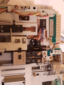
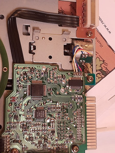
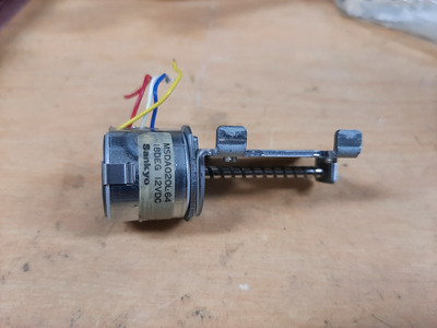
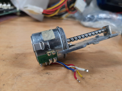
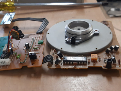
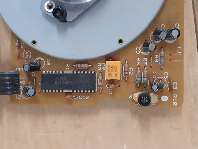
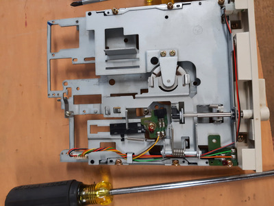
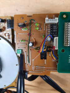
I am going through my collection and trying to find a 5.25" drive for this epson equity machine I am working on. So far out of my 4 5.25" drives, 3 have the same fault, no spindle motor activity. The head seeks on POST, but anytime a disk is inserted it is like the motor just doesn't get the signal to turn on. The 4 drive does spin the motor, but the locking arm mech is busted. Unfortunately all 4 drives are all different brands, so no cobbling together for a working drive. I have since changed floppy cables, controllers, and even moved over to a slot 1 pII board with built in FDC to have a sanity check , and all 3 drives will light up like they are accessing the drive, but the motor is just dead. I checked for good 12volts on the boards where the motor is attached.

Now my question, do you think the original epson floppy controller killed the motor driver IC perhaps? I find it pretty unlikely to have 3 drives with the exact same fault and one of the drives I know 100 percent was good that was pulled from a 486 years ago and stored in a box with foam in my office, so good conditions.

Reply 1 of 25, by Deunan

User metadata
Rank Oldbie
Rank
Oldbie

I've never heard of such a thing. And it can be tested with a PSU and a few wires (usually the easiest way is to stick some short wires into the plug on the other end of the flat ribbon cable - motor on and select to GND).

Some floppy drives will not spin the motor if the drive is not selected, or (if there is a media presence sensor) a floppy is not inserted. In general I would first check if the spindle can actually rotate (with a finger), then check the cable, floppy drive jumpers and finally BIOS settings.

That being said one rather common failure point of floppy drives (this includes some early 3.5" ones as well) is leaking electrolytic capacitors that can corrode and "eat away" traces. The spindle motor sub-PCB has at least one power smoothing cap that can cause that. Another common problem is failure of the ceramic resonator that sets the fundamental frequency for the motor IC.

Reply 2 of 25, by lowlytech

User metadata
Rank Member
Rank
Member

All the motors do turn by hand (all direct drive) and i did apply voltage to the teac 55gfr unit at the motor leads and the motor did start to spin. Your right about caps, the panasonic unit had 2 surface mount caps that i did replace that were pretty yucky looking and were without a doubt leaking. I cleaned up the area checked traces and reapplied mask to the bare copper but it still wouldn't spin the disk.

Reply 3 of 25, by Deunan

User metadata
Rank Oldbie
Rank
Oldbie

Most (but not all, esp. the very early ones) 5.25" floppy drives would spin the motor for a few seconds when floppy insertion is detected by media or WP sensor. This is to help centering of the magnetic media vs spindle. No spin on a late HD drive would be suspicious and I would investigate the sensors (dirty/oxidated contacts or optical barriers packed with dust). If the motor has its own sub-PCB then the cables will have GND, +12V, sometimes +5V, and one of the other ones is motor on signal. You can pretty easily identify the the power lines with an ohm meter (vs power plug) and try running the motor in stand-alone mode. In some cases all you need is apply power and the pull-up/down resistors will actually drive the on signal and make the motor run. If not use 100-500 ohm resistor and apply GND or +5V to other wires via that resistor, you should find the motor on signal that way. Or just find a schematic for that particular drive model. Obviously any such experiments should be done with the sub-PCB plug disconnected from the rest of the drive.

If you can't get the motor to run inspect the traces, cables, and soldering for cracks (rare but happens). If it does run then it's either the sensors or one of the ICs on the man PCB is not happy.

Reply 4 of 25, by Jo22

User metadata
Rank l33t++
Rank
l33t++

I think the same, some floppy drives would start spinning for 1-2 secs if a floppy was inserted, some wouldn't.
I think there was a jumper setting for that, even. But that was so long ago..

"Time, it seems, doesn't flow. For some it's fast, for some it's slow.
In what to one race is no time at all, another race can rise and fall..." - The Minstrel

//My video channel//

Reply 5 of 25, by lowlytech

User metadata
Rank Member
Rank
Member

Thanks Deunan, I will get the air compressor out and do a real through cleaning of all 3 drives and maybe that will help with any sensors in there. I did confirm with an ohm meter that I do indeed get GND, 5 and 12 volts to the sub pcb that has the spindle motor. Haven't checked the 2 signal lines as of yet.

Reply 6 of 25, by lowlytech

User metadata
Rank Member
Rank
Member

Jo22, Yeah there is definitely no shortage of jumpers on these (Newtronics D509V, Teac 55-GFR, panasonic JU-475-3c29, and Toshiba FDD6784L3B) My gut is telling me I have something configured wrong, but I do remember that the newtronics drive was in normal working condition and now it doesn't spin the motor like the teac and the toshiba, that is what had me worried that somehow I was killing these with some faulty controller.

Reply 7 of 25, by lowlytech

User metadata
Rank Member
Rank
Member

Got all the drives cleaned up really well, and inspected every trace/sensor I can find and I still can't get any of these drives in a working state. I did noticed the Newtronics D509V drive will make a very low hum in the head motor area whenever power is applied and after 15-20 seconds the motor does gets quite warm. Floppy controller cable either attached or not has the same result. So does this indicate that that motor is bad or I guess it could be something on the controller is telling it to do that? I loosened the motor to verify that the head assembly isn't stuck. Also put some sewing oil on the base of that motor but didn't seem to help or change anything.

Guess I may be at that point to start looking out in the wild for a 1.2Mb 5.25 drive. Does anyone have a stockpile if 1.2 drives they would consider trading or selling one? My collection of 1.44 3.5" drives is somewhere close to 20 or so, maybe a 5 for 1 deal?

Reply 8 of 25, by Deunan

User metadata
Rank Oldbie
Rank
Oldbie
lowlytech wrote on 2023-10-21, 14:57:

Newtronics D509V drive will make a very low hum in the head motor area whenever power is applied and after 15-20 seconds the motor does gets quite warm.

Is it still turning easily in that state, or does it seem like a brake is applied? This could be the IC dying but I would first check if it gets stable clock from the ceramic resonator. You'll need a scope for that.
D509V needs a jumper in either MM or MS position for to motor to work (and for PC it needs to be set to MM).

Reply 9 of 25, by lowlytech

User metadata
Rank Member
Rank
Member
Deunan wrote on 2023-10-21, 19:07:
lowlytech wrote on 2023-10-21, 14:57:

Newtronics D509V drive will make a very low hum in the head motor area whenever power is applied and after 15-20 seconds the motor does gets quite warm.

Is it still turning easily in that state, or does it seem like a brake is applied? This could be the IC dying but I would first check if it gets stable clock from the ceramic resonator. You'll need a scope for that.
D509V needs a jumper in either MM or MS position for to motor to work (and for PC it needs to be set to MM).

Just to make sure I am not confusing you (since I keep jumping around to 4 different drives) this Newtronics is not the spindle motor, of course I haven't seen it rotate yet so it may be bad too. When the power is applied the head stepper motor is what sounds like it isn't happy. I took the motor completely out and unlatched the back and the center pin with the worm gear on it. It came out and had two magnet cylinders on it and looked pretty normal, but I am no motor guy and not sure what I am looking at. Put it all together after a good clean and it still doesn't want to move or sound happy. When I reattached the drive heads it wasn't at track 0, and the motor tried to move the heads for a split second on power on, but then stopped.

Yes with the motor outside the drive it does spin. I wouldn't say it is freely spinning, seems to go one way but not the other. Have a scope if you show me what crystal I need to measure.

20231021_204221.jpg
Filename
20231021_204221.jpg
File size
997.09 KiB
Views
868 views
File license
Public domain
20231021_203910.jpg
Filename
20231021_203910.jpg
File size
1.45 MiB
Views
868 views
File license
Public domain

Reply 10 of 25, by Horun

User metadata
Rank l33t++
Rank
l33t++
lowlytech wrote on 2023-10-22, 01:50:

Just to make sure I am not confusing you (since I keep jumping around to 4 different drives) this Newtronics is not the spindle motor, of course I haven't seen it rotate yet so it may be bad too. When the power is applied the head stepper motor is what sounds like it isn't happy. I took the motor completely out and unlatched the back and the center pin with the worm gear on it. It came out and had two magnet cylinders on it and looked pretty normal, but I am no motor guy and not sure what I am looking at. Put it all together after a good clean and it still doesn't want to move or sound happy. When I reattached the drive heads it wasn't at track 0, and the motor tried to move the heads for a split second on power on, but then stopped.

Yes with the motor outside the drive it does spin. I wouldn't say it is freely spinning, seems to go one way but not the other. Have a scope if you show me what crystal I need to measure.

Something is not right. Both Platter motor (easy to test assembled) and head motor (when removed) should spin semi freely both directions. Both are usually brushless motors that the field coils are controlled by the electronics, nothing should prevent physically rotating either direction with no power...

Hate posting a reply and then have to edit it because it made no sense 😁 First computer was an IBM 3270 workstation with CGA monitor. Stuff: https://archive.org/details/@horun

Reply 11 of 25, by lowlytech

User metadata
Rank Member
Rank
Member

Spindle (bigger motor that spins the disk) does spin freely in both directions by hand. The worm drive (one that moves the heads)on the other hand I would say has a gritty feel. If I can get back out to the shop tonight I will try and take the worm motor out again and take a picture of it.

Reply 12 of 25, by Horun

User metadata
Rank l33t++
Rank
l33t++

OK, since the head (worm) motor has to be able to freely rotate both directions to move head in and out when under power, it must be free to rotate both directions.
If the head motor is a DC "brush" type maybe the brushes are worn and that makes it not want to freely move one way and that is the "gritty feel".... just a thought. If brushless then something else is wrong with it....

Hate posting a reply and then have to edit it because it made no sense 😁 First computer was an IBM 3270 workstation with CGA monitor. Stuff: https://archive.org/details/@horun

Reply 13 of 25, by lowlytech

User metadata
Rank Member
Rank
Member

Here is the motor in question. I don't know what I am looking at or what area to focus on. Let me know if you need better pictures.

Thanks again..

20231021_224236.jpg
Filename
20231021_224236.jpg
File size
965.47 KiB
Views
808 views
File license
Public domain
20231021_224304.jpg
Filename
20231021_224304.jpg
File size
974.6 KiB
Views
808 views
File license
Public domain
20231021_224333.jpg
Filename
20231021_224333.jpg
File size
1.06 MiB
Views
808 views
File license
Public domain
20231021_224433.jpg
Filename
20231021_224433.jpg
File size
1.05 MiB
Views
808 views
File license
Public domain
20231021_224502.jpg
Filename
20231021_224502.jpg
File size
956.47 KiB
Views
808 views
File license
Public domain

Edit... I may be imagining things, but this worm shaft looks kind of bent ever so slightly?? Maybe not, .. very slight it would seem

Reply 14 of 25, by Deunan

User metadata
Rank Oldbie
Rank
Oldbie
lowlytech wrote on 2023-10-22, 03:57:

Here is the motor in question. I don't know what I am looking at or what area to focus on. Let me know if you need better pictures.
(...) I may be imagining things, but this worm shaft looks kind of bent ever so slightly?? Maybe not, .. very slight it would seem

It's not easily bent and there are no forces in the drive that could do it. Probably an optical illusion.
I sure hope you didn't loose the tiny ball that sits at the end of the shaft? This is a "ball bearing", just this one ball and some grease. The worm screw will not have proper support at the end without it...

You will need to do full head alignment now that you took the stepper motor out, but that's assuming the drive works at all. This motor should not get hot (or even substantially warm) - that would mean the 12V is not being reduced to 5V (with possible further current limit) once the stepping is done. Which can happen if the IC doing all the timings (step, spin-up, write and erase delays, etc) is not getting clock. This is mixed SMD and THT PCB, the chips and most resistors and capacitors are SMD but larger parts - chokes, electrolytic caps, power resistors and the ceramic resonator - are on the other side.

Reply 15 of 25, by lowlytech

User metadata
Rank Member
Rank
Member

Thanks for all the explanations Deunan, very informative. Let me get a picture uploaded of the other side of the PCB and I can sure test for a clock if you can help point out what component...

Well everything was reversed, so the only components you could see was the backside of the pcb. The point of no return is when I had to remove the track 0 sensor to get the boards out. I can only imagine how difficult it is to test this with power applied and connected to all the components.

Yes on the worm drive there was a small cap on the end that it went into. It did fall out when I removed the motor, but I am keeping track of it.

Thanks..

20231022_082027.jpg
Filename
20231022_082027.jpg
File size
932.32 KiB
Views
744 views
File license
Public domain
20231022_082034.jpg
Filename
20231022_082034.jpg
File size
982.77 KiB
Views
744 views
File license
Public domain
20231022_082041.jpg
Filename
20231022_082041.jpg
File size
948.5 KiB
Views
744 views
File license
Public domain
20231022_082048.jpg
Filename
20231022_082048.jpg
File size
1.11 MiB
Views
744 views
File license
Public domain

Reply 16 of 25, by Deunan

User metadata
Rank Oldbie
Rank
Oldbie
lowlytech wrote on 2023-10-22, 13:52:

Let me get a picture uploaded of the other side of the PCB and I can sure test for a clock if you can help point out what component...

There's 2 ceramic resonators here - one green, for the "main" IC and the motor PCB has its own one, this one is orange. You should be able to see a nice, clean sine or square wave on the scope on at least one of the pins - for that it's best to use 10:1 probe as direct connection to scope input might load the circuit too much and stop oscillations.

I can't remember the frequencies now. Motor PCB frequency might seem odd - that's OK as long as it's stable. If you see both clocks then sadly I would suspect the IC itself - although that would be odd, these are pretty mature tech on mastered process, they rarely ever die (unlike the earlier mixed TTL and 1st gen LSI generation drives).

EDIT: One more thing, this drive seems to be using mechanical media presence detector/switch. Now this particular type might be more robust but in general the mechanical switches in old FDDs are prone to oxidation and high (or very unstable) contact resistance.

Reply 17 of 25, by lowlytech

User metadata
Rank Member
Rank
Member

I tested the floppy disk change switch and it still seems to function okay. I hooked the drive to power without the heads attached. I got activity on the green crystal, both leads were the same. But the yellow one seems totally dead or no change on the scope. I marked the solder side where that yellow crystal is.

20231022_230450.jpg
Filename
20231022_230450.jpg
File size
1.28 MiB
Views
686 views
File license
Public domain
20231022_230500.jpg
Filename
20231022_230500.jpg
File size
1.42 MiB
Views
686 views
File license
Public domain
20231022_231249.jpg
Filename
20231022_231249.jpg
File size
1.23 MiB
Views
686 views
File license
Public domain
20231022_231300a.jpg
Filename
20231022_231300a.jpg
File size
1.43 MiB
Views
686 views
File license
Public domain

Reply 19 of 25, by Deunan

User metadata
Rank Oldbie
Rank
Oldbie
lowlytech wrote on 2023-10-23, 04:47:

But the yellow one seems totally dead or no change on the scope. I marked the solder side where that yellow crystal is.

There is some sort of white residue between IC pins that connect to the resonator. Could be just enough to affect the circuit - use some old toothbrush to clean the PCB, make sure there is nice, clean separation between the pins. If there's still no clock there then the resonator itself is suspect - you could try a transplant from another drive (if only to test the theory).