Reply 20 of 31, by JUCED
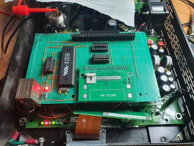
Hello guys! I'm finally back. I built a board with VT82C42 IC but sadly i had no success. I tried to follow step by step what the datasheet says (about the controller initialization) but it seems that something is wrong. The first part says:
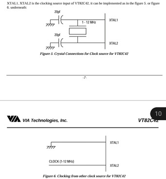
"The internal timer counting is based on an 8Mhz clock input from X1, X2 ( or X2, with X1 connected to
ground). After the deassertion of RESET#, the VT82C42 will drive high at pin P23 and pin P27. After 6 ms (6
x 8 clocks) of driving, the VT82C42 will check on pins T1 & P10; if both pins are low, then the VT82C42
will switch to PS/2 mode. Otherwise, the VT82C42 will remain in AT mode.
If the VT82C42 is in AT mode after the self test, then it will drive P24 and P25 low with all other ports high.
If the VT82C42 is in PS/2 mode, then it will drive P24, P25, P22, and P27 low with all other ports high."
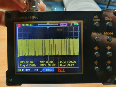
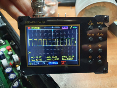
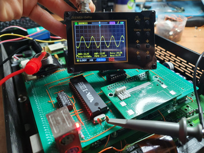
I have 8Mhz clock on X2 (i made an onboard oscillator using a crystal and a couple of capacitors, so no external clock). RESET# seems to come correctly at startup. Then P23 and P27 go HIGH. After this, it should check on T1 and P10, they are both low but for some reason the VT82C42 doesn't initialize correctly (it seems that it's not in PS2 or AT mode). I should have P24, P25, P22, and P27 low, instead i have P24, P25 low and P22, P27 high.
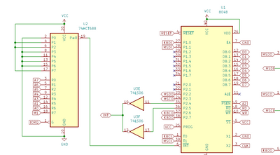
Everything is connected correctly, i followed the previous schematics:
D0-D7 from the ISA BUS to D0-D7 (pins 12-19)
A2 from the ISA BUS to A0 (pin 9)
RD to RD (pin 😎
WR to WR (pin 10)
RESET to RESET (pin 4)
Pin 7 and 20 to GND
Pin 5, 25, 26 and 40 to VCC
CS# is connected to KBCS# of the STPC Elite (from the datasheet: "KBCS# Keyboard Chip Select. This signal is asserted if a keyboard access is decoded during a I/O cycle")
And all the mouse/keyboard interface is correctly wired to a double PS/2 connector.