VOGONS


First post, by kevmif

User metadata
Rank Newbie
Rank
Newbie

Hi all!

I just installed Win98 on a GA-586HX pimped out with a 233MMX and 128MB RAM (6 RAM slots woooo).
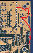
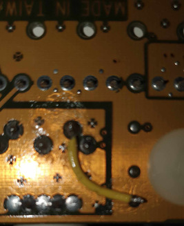
Only this version of the board has no PS/2 out - all good, it supports USB. I don't have the original headers though. The more modern USB headers have 10 pins with a blank for key. The board has 8 pins.

No dramas I thought. Red is 5v, black is ground. Easy. Got out the old multimeter and checked what I thought was pin 1 and sure enough, there was 5v across pins 1 and 4.
Then I went over to pins 5-8, directly opposite, but surprisingly, I got -5v. Yup, the pin out of the second row of pins appears reversed.

Is this right? Did these early USB boards use a different pinout meaning I cannot use a modern USB header?
I'll see if I can make something up to test but if accidentally I reverse the polarity, will it damage by board, or just whatever unfortunate piece of hardware I plug in to it?

Thanks

Reply 1 of 14, by Dorunkāku

User metadata
Rank Newbie
Rank
Newbie

You got it right.
Early USB headers had 8 pins, with the second row being the reverse of the first one so you plug in the plug both ways and it would work. You can not use a modern 10 pin keyed plug. Get a USB slot plate with two seperate 5x1 plugs and adapt that.
Also the PS2 header should be located under the COM port headers.

Reply 2 of 14, by kevmif

User metadata
Rank Newbie
Rank
Newbie

Thanks! I made an adaptor to get one port working with my modern 10 pin plug. Should be trivial to do the same and get the second one working.
Super glad I got the multimeter out to check. Thanks so much for confirming how the old 8 pin headers worked. Glad they switched to a 10 pin keyed design because frankly whomever came up with the 8 pin header with reversed rows needs to be bludgeoned with a keyboard 😜

Reply 3 of 14, by kevmif

User metadata
Rank Newbie
Rank
Newbie

Somehow I screwed up wiring the second port. I was very careful with my voltage wires thinking the signal wires would be no worries and I could fix them later if wrong.
Either way, something shorted and now I have low voltage (2v instead of 5v) on the keyboard port (obviously it doesn't work). The USB ports also have no voltage (1 volt per port).
I've visually inspected the area as best I can with nothing standing out as obviously burnt, but I'm confident at least one of the SMDs is dead / shorted.

Not at all confident I can diagnose let alone repair this one. Should I try to sell it 'for parts' or is there a chance I can resurrect it?
Damn shame as this was proving to be a pretty awesome 233MMX build. Looks like I'm back to using a VX board...boo.

Reply 4 of 14, by weedeewee

User metadata
Rank l33t
Rank
l33t

There seems to be a fuse right next to the keyboard connector. Measure it's resistance. It should be ~0.

Anything else to check will need better photos.

Right to repair is fundamental. You own it, you're allowed to fix it.
How To Ask Questions The Smart Way
Do not ask Why !
https://www.vogonswiki.com/index.php/Serial_port

Reply 5 of 14, by kevmif

User metadata
Rank Newbie
Rank
Newbie

Oh, thats what that thing is? Yeah, very close to zero (multimeter beeped to indicate continuity but there was some very minimal resistance (a few ohm).

Does this help?

https://www.dropbox.com/scl/fi/uuj6ijp57t34v4 … sp9hr3dz9f&dl=0

Being a multi layered PCB, it is effectively impossible to follow traces to identify potentially faulty components. About the only thing I can realistically replace is that one capacitor....

Reply 6 of 14, by Dorunkāku

User metadata
Rank Newbie
Rank
Newbie
kevmif wrote on 2024-02-17, 09:50:

About the only thing I can realistically replace is that one capacitor....

I am confident that, that is about the skill level you need to repair this board.
Your voltage measurements don't make sense to me. What would help is measuring the resistance between the +5Volt on the AT power connector and the +5Volt on the Keyboard port. And measuring the resistance between the on the AT power connector and both the +5Volt pins on the USB connector. All three measurements should be close to 0 Ohms. Measure with the powersupply disconnected from the board.

If any of those measurement are not close to 0 Ohms you probably destroyed a +5Volt track on the PCB, which is not a big deal.

Reply 7 of 14, by kevmif

User metadata
Rank Newbie
Rank
Newbie

Thanks Dorunkāku.

I have tested as per your suggestion and here are the results.

On a WORKING board (VX chipset). I get full continuity between the 5v on the AT Keyboard port and any 5v pin on the P8/P9.
On the HX board I broke, I get a flicker of continuity, then the resistance climbs to about 3o0 ohms. Same for the 5v on the USB.

You say a destroyed 5v track is not a big deal, but these are multi layered boards (not like a good old 486!) and my skill-set is rudimentary at best. I assume I can't just patch a wire from one of the P8/P9 connectors direct to the keyboard (or can I?).

I'd love to be able to get this working again but I don't want to further butcher it in the process - I would be appreciative of any suggestions or advice provided. Thanks

Reply 9 of 14, by Dorunkāku

User metadata
Rank Newbie
Rank
Newbie

I made a diagram how the keyboard and PS2 mouse port should be connected.
The lines marked 1,3 and 4 are internal traces and the line marked 2 is a fuse.
The fuse should protect the motherboard and powersupply from shorts in the keyboard, mouse or USB devices.

You said the fuse still measured 0 Ohms and you dont have +5 Volt on the keyboard connector which suggests the connection marked with line 1 is broken. If that is true than solder a insulated piece of wire between the endpoints of line 1.

Attachments

Last edited by Dorunkāku on 2024-02-21, 23:02. Edited 1 time in total.

Reply 10 of 14, by Paar

User metadata
Rank Member
Rank
Member

I modified this board the same way year or two ago and by mistake put USB connector the wrong way on, which created a short and the fuse resistor near keyboard burned. There is a page about modding this board and they have the proper fuse value needed (for archiving purposes, it's 2.2Ohm with 5% tolerance).

Reply 11 of 14, by kevmif

User metadata
Rank Newbie
Rank
Newbie

Dorunkāku - thank you so, so much for your patience and excellent explanation.

Believe it or not, the break was between the fuse and the 5v. Strange right? Why didn't the fuse die?

crappy solder job.jpg
Filename
crappy solder job.jpg
File size
125.49 KiB
Views
253 views
File license
Public domain

I did my best to solder a wire and it seems to work. Nothing blew up and the keyboard was active again! I was really worried my shitty soldering job would link 5v to ground! Guessing I'd know immediately if I'd done that, even just a little!
I'll do some more thorough testing tomorrow.

I'll still have dead USB ports, but no big deal. Bit pissed this board doesn't have a PS/2 port - if it did, I would never have bothered with the USB. Other revisions of this board have it, but not the v2.01 it seems....
Hopefully the com ports aren't dead... we'll see I guess.

Thank you again.

Reply 12 of 14, by weedeewee

User metadata
Rank l33t
Rank
l33t

Looking at the photo on theretroweb, that trace between keyboard connector 5v & fuse seems to be located on the top side of the board, mostly underneath the keyboard connector.

Good you got it working again. Do you now also have 5v on the usb connector again?

Right to repair is fundamental. You own it, you're allowed to fix it.
How To Ask Questions The Smart Way
Do not ask Why !
https://www.vogonswiki.com/index.php/Serial_port

Reply 13 of 14, by Dorunkāku

User metadata
Rank Newbie
Rank
Newbie

Well done!

kevmif wrote on 2024-02-22, 11:50:

...
Bit pissed this board doesn't have a PS/2 port
...

But it has a PS2 port header.
And the fuse is a polyfuse. They reset after a while.

Reply 14 of 14, by kevmif

User metadata
Rank Newbie
Rank
Newbie

Looks like I have power to the USB ports too - great. Though I am too scared to try wiring them up again as I thought I was sure about the voltages last time. The only thing I wasn't 100% sure of was if I had the data lines right. Surely that wouldn't fry things? Would it?

Unless... could the header I used have switched the wiring between the two ports? same colour wire for the opposing pins so I assumed however wired the first row, I would reverse for the second row... It is a USB 2.0 header from a later board.

Dorunkāku - my board appears to have a fan header where the PS/2 port would go. Don't tell me some boards have 4 pin PS/2 headers that look like fan headers? Wait a sec, this board is way too old for 4 pin fan headers, so okay, I guess they designed a different header for the v2 model of the board instead of just 4 pins.... Time to test that out and hope I don't fry anything else. Edit: Success. Identified VCC and GND, then guessed data and clock and got it first go.