VOGONS


First post, by GigAHerZ

User metadata
Rank Oldbie
Rank
Oldbie

Hi all!

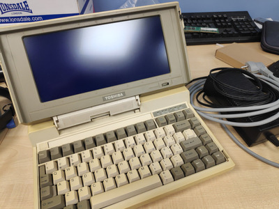
I have acquired this amazing portable 8086 machine to fix!
I have validated it (through beeps, floppy drive activity and keyboard input) that it is working. (I have nothing to connect to CGA display port)
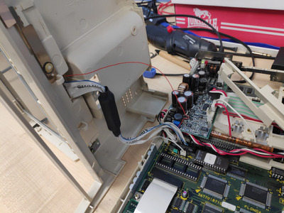
All voltages (including negative 22V that should be necessary for LCD) are good.

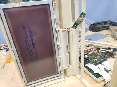
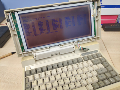
But the LCD panel is unfortunately not working. It is whining (in correlation with "Brightness" knob in front) and flickering some horizontal lines. The lines seem to be flickering more, when i physically tap on the screen. The panel seems to be perfect.
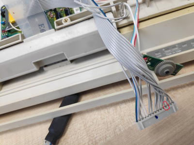
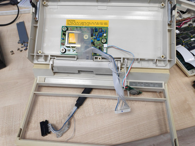
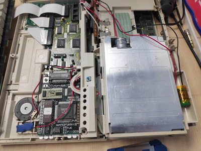
I opened it up and behind the LCD screen, there was a PCB with some transformer and 2 very suspicious capacitors. I replaced the capacitors with new ones, but the issue remains.
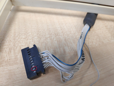
From the behavior, it almost seems like some cabling has just gotten partially unplugged... But everything is connected properly.

Link to video: https://youtu.be/Nqn76LitlRo
Starting from 0:13, the whine can be heard better. I think it comes from the additional PCB behind the panel with transformer.

Unfortunately, i don't have such spidey-senses like Adrian Black or others like him. I do hold soldering iron in my hand pretty confidently, though.
Maybe any of you could suggest something to test, try, check?

I've attached disassembly instructions to this post as well.

EDIT: Made one more video. (The damn youtube made it as shorts instead of video and has no option to rotate the video... please forgive me)
A hovering hand changes how the screen flickers. It looks even more like some disconnected wire somewhere...
https://youtube.com/shorts/CFS7ymU87c8

Attachments

"640K ought to be enough for anybody." - And i intend to get every last bit out of it even after loading every damn driver!

Reply 2 of 10, by GigAHerZ

User metadata
Rank Oldbie
Rank
Oldbie
giantclam wrote on 2024-01-26, 08:58:

Further dis-assembly required to divine why hand proximity is doing that.

Sure! What parts do you want to see? I can make pictures, measure some voltages and continuities, etc. (I don't have oscilloscope, unfortunately)

"640K ought to be enough for anybody." - And i intend to get every last bit out of it even after loading every damn driver!

Reply 3 of 10, by giantclam

User metadata
Rank Member
Rank
Member

Looking at the 2nd vid, I'm doing a 'Sunmer-Miller' and wondering why it is so.... typically, hand proximity introduces noise, and normally a component of that is the mains AC frequency (50 or 60Hz) ~ looking at the display, and how it tries to sync when hand is close, my immediate thought is something to do with the V-sync signal.... ie; display behavior is typical of lost v-sync. You could be right, it might be a broken wire, but the moment you say that you have to include the cable between mainboard and display .... this would be where I'd start ; verifying that cable between display and connector.... but getting that far, something else may become obvious along the way.

Reply 4 of 10, by GigAHerZ

User metadata
Rank Oldbie
Rank
Oldbie

I think i have found the culprit. The cable doesn't give me a beep where it should.
I've marked the pins on both sides which i expect a beep. I tracked the line by beeping through neighboring lines and this is that one line that has a gap.

What would be the best action to take here? The cable itself is pretty standard, but the connectors are something I'm not too sure about making my own. Are they standard? Can i buy a kit of connectors and fabricate my own cable? (NB, i also don't know, what's under the black cover in the middle of the cable...)

Attachments

"640K ought to be enough for anybody." - And i intend to get every last bit out of it even after loading every damn driver!

Reply 5 of 10, by giantclam

User metadata
Rank Member
Rank
Member

Probably your best bet is to just replace that wire ... although (carefully) cutting off that heatshrink and having a look inside would be worth the effort ~ idea is to try find exactly where the break is, in case other conductors in that cable are being stressed in a similar way. Cutting/splicing a wire to replace it will be fine.... but they put that heatshrink there for a reason, and it's best to find out if there's anything critical there =)

Reply 6 of 10, by Tiido

User metadata
Rank l33t
Rank
l33t

That break is probably gonna be where the flexy part is between the two sides, and there's a likelyhood that others might follow eventually too. I would do two snips at a comfortable distance from both ends (few cm is good) and solder a new wire between. The black bit probably has some ferrites under it for EMC reasons, but you can ignore that for starters.

T-04YBSC, a new YMF71x based sound card & Official VOGONS thread about it
Newly made 4MB 60ns 30pin SIMMs ~
mida sa loed ? nagunii aru ei saa 😜

Reply 7 of 10, by GigAHerZ

User metadata
Rank Oldbie
Rank
Oldbie

Just added a random thin wire (single thread - can't leave it there) and jammed each end between the connectors and it works!

I'm still thinking of how to maybe create complete new cable. there are 3 different connectors and one ribbon-cable involved. If i could get the connectors and connect the ribbon cable ends myself, i could create completely new cable for it...

Attachments

"640K ought to be enough for anybody." - And i intend to get every last bit out of it even after loading every damn driver!

Reply 8 of 10, by Tiido

User metadata
Rank l33t
Rank
l33t

The connectors are all standard, you can buy housings (or reuse existing ones) and also the crimpable pins and make custom cables. The dedicated crimping tools can be very very expensive, but there are ways to do stuff without that expense 🤣
It can take some effort to accurately identify the connectors though, there are bazillion of them and they're not compatible among each other...

T-04YBSC, a new YMF71x based sound card & Official VOGONS thread about it
Newly made 4MB 60ns 30pin SIMMs ~
mida sa loed ? nagunii aru ei saa 😜

Reply 9 of 10, by GigAHerZ

User metadata
Rank Oldbie
Rank
Oldbie

Booted up from Toshiba's MS-DOS 3.3 720k disk!
Has some issues that when screen-scroll happens, it all goes fully dark. Typing "cls" command will restore normal visuals.

Bought some bios/standby battery solutions (1x2.4V + 1x4.8V) and was able to cut open main battery compartment - 6xNi-Cd. So quite easily replaceable with 2x18650 with appropriate controller. There's plenty of room for that, too, in original battery case.

Attachments

"640K ought to be enough for anybody." - And i intend to get every last bit out of it even after loading every damn driver!

Reply 10 of 10, by GigAHerZ

User metadata
Rank Oldbie
Rank
Oldbie

New batteries are in. Waiting for some capacitors to do a full capacitor replacement on PSU.

... and a 2S 18650 controller board to create a new Li-Ion based battery for this machine. 😉

Attachments

"640K ought to be enough for anybody." - And i intend to get every last bit out of it even after loading every damn driver!