VOGONS


ISA Riser problems

Topic actions

Reply 20 of 42, by Boohyaka

User metadata
Rank Oldbie
Rank
Oldbie
TheMobRules wrote on 2024-02-05, 02:12:

Maybe the OP is running an overclocked ISA bus or something that in combination with the riser card can end up affecting signal integrity?

Thank you for your feedback. The ISA bus is devinitely not overclocked, but maybe this motherboard has some other sensitivity that make it incompatible with the cheap design?

Reply 21 of 42, by weedeewee

User metadata
Rank l33t
Rank
l33t

The riser looks a lot like the one I have in an olivetti pcs40 branded case. It's currently housing a 386dx40 mainboard (pcchips m321) and I haven't experienced any problems like the ones you've described.

Right to repair is fundamental. You own it, you're allowed to fix it.
How To Ask Questions The Smart Way
Do not ask Why !
https://www.vogonswiki.com/index.php/Serial_port

Reply 22 of 42, by Boohyaka

User metadata
Rank Oldbie
Rank
Oldbie

Here's some closure - I've received and installed the 386, and it has 0 problem with the existing ISA riser so that's good news! I can notice a little noise on the VGA signal that I assume is because of the lack of proper grounding and/or capacitors. I may try to improve it down the road (or keep an eye out for a better riser) but for the time being, it works! Thanks for all the input and great info.

Reply 23 of 42, by kingcake

User metadata
Rank Oldbie
Rank
Oldbie

No ground is extremely common on risers (you don't want big ground loops on digital stuff) and is not a problem. It's grounded through the motherboard. It's the caps for the VGA noise.

I restore tons of Packard Bells and they all have ISA/PISA risers. I replace all the 10uF cheapo electrolytics on the risers with 22uF low ESR polymer caps and the VGA signal goes from noisy to clean.

Reply 24 of 42, by Boohyaka

User metadata
Rank Oldbie
Rank
Oldbie

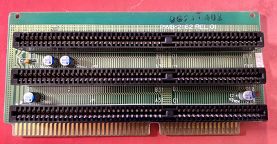
ok, thanks for the good tip. Mine as 0 capacitors right now 😁 but it has what looks like some cap potential locations.

Do you think it could help trying to install some caps on these spots? I will need to take it out to probe for continuity, but maybe you already know what I should look for? Thanks!

Untitled.png
Filename
Untitled.png
File size
1.66 MiB
Views
343 views
File license
GPL-2.0-or-later
Last edited by Boohyaka on 2024-02-28, 18:35. Edited 1 time in total.

Reply 27 of 42, by Boohyaka

User metadata
Rank Oldbie
Rank
Oldbie

thanks again. How I can make sure those spots are actually well connected and suitable spots for caps? What should I be looking for?
Btw looks like there may be another set of 2 or 3 above the middle ISA connector.

Reply 28 of 42, by weedeewee

User metadata
Rank l33t
Rank
l33t
Boohyaka wrote on 2024-02-28, 18:39:

thanks again. How I can make sure those spots are actually well connected and suitable spots for caps? What should I be looking for?
Btw looks like there may be another set of 2 or 3 above the middle ISA connector.

Looking at the photo, It would seem that both locations are occupied by the ISA slot on the other side, so soldering the capacitors will only work if you leave some of the legs out. (maybe bend'm over and lay the capacitors flat against the board)

edit, on second look, maybe not the ones on the end, but definitely the ones in the middle 😀

Right to repair is fundamental. You own it, you're allowed to fix it.
How To Ask Questions The Smart Way
Do not ask Why !
https://www.vogonswiki.com/index.php/Serial_port

Reply 29 of 42, by kingcake

User metadata
Rank Oldbie
Rank
Oldbie
weedeewee wrote on 2024-02-28, 19:08:
Boohyaka wrote on 2024-02-28, 18:39:

thanks again. How I can make sure those spots are actually well connected and suitable spots for caps? What should I be looking for?
Btw looks like there may be another set of 2 or 3 above the middle ISA connector.

Looking at the photo, It would seem that both locations are occupied by the ISA slot on the other side, so soldering the capacitors will only work if you leave some of the legs out. (maybe bend'm over and lay the capacitors flat against the board)

They definitely are not. Not sure what pic you are looking at. Those are clearly bypass caps for 2.0/2.5mm leg spacing caps. With one leg in the ground flood fill. Probably bypassing +5,-5,+12 if I had to guess.

Reply 30 of 42, by weedeewee

User metadata
Rank l33t
Rank
l33t
kingcake wrote on 2024-02-28, 22:36:
weedeewee wrote on 2024-02-28, 19:08:
Boohyaka wrote on 2024-02-28, 18:39:

thanks again. How I can make sure those spots are actually well connected and suitable spots for caps? What should I be looking for?
Btw looks like there may be another set of 2 or 3 above the middle ISA connector.

Looking at the photo, It would seem that both locations are occupied by the ISA slot on the other side, so soldering the capacitors will only work if you leave some of the legs out. (maybe bend'm over and lay the capacitors flat against the board)

They definitely are not. Not sure what pic you are looking at. Those are clearly bypass caps for 2.0/2.5mm leg spacing caps. With one leg in the ground flood fill. Probably bypassing +5,-5,+12 if I had to guess.

You missed the last line of my previous comment.

but do not tell me exactly how you plan on fitting the capacitor in between the 8 & 16bit section of the ISA slot.

Right to repair is fundamental. You own it, you're allowed to fix it.
How To Ask Questions The Smart Way
Do not ask Why !
https://www.vogonswiki.com/index.php/Serial_port

Reply 31 of 42, by Boohyaka

User metadata
Rank Oldbie
Rank
Oldbie
kingcake wrote on 2024-02-28, 22:36:

They definitely are not. Not sure what pic you are looking at. Those are clearly bypass caps for 2.0/2.5mm leg spacing caps. With one leg in the ground flood fill. Probably bypassing +5,-5,+12 if I had to guess.

So I received the caps, and took the card out for some multimeter work.

There are only three spots, as guessed before. All three are GND and +5V. All other extra spots noticed before are all ground.
On the 3 spots, the two outer ones are free on the other side and can easily be installed, but the middle one is indeed covered by the ISA slot on the opposite side, but I could definitely fit it sideways or on short legs I think.

The question I have now is...if all 3 spots are +5V, does it matter or is it useful to populate the three spots with caps?

And just to be an extra-extra-careful noob as there's no marking on the board: + to 5V, - to ground? 😁

Reply 32 of 42, by Tiido

User metadata
Rank l33t
Rank
l33t

You fill all spots not just one, because of inductance, the further away part is less effective or totally ineffective depending on freq it has to work with.

And yes, + to +, and - to ground, or you'll make some stinky fireworks 🤣

EDIT: fixed a stupid typo

Last edited by Tiido on 2024-03-06, 21:17. Edited 1 time in total.

T-04YBSC, a new YMF71x based sound card & Official VOGONS thread about it
Newly made 4MB 60ns 30pin SIMMs ~
mida sa loed ? nagunii aru ei saa 😜

Reply 33 of 42, by Boohyaka

User metadata
Rank Oldbie
Rank
Oldbie

Thanks Tiido, better safe than sorry 😀

It's a success! I wouldn't call it perfect, I have a still visible somewhat "higher frequency" VGA noise if that makes sense, but it's still substantially less visible! Is it something that could still be improved by choosing different caps? Or is it the best I can do right now with this board as only +5V can be capped?

Coming from a no electronics background I just can't get enough of the stuff. I am still very much in the "how" phase and now have a pretty OK grasp of soldering, having recapped a few complete boards successfully, a few other fixes here and there, and it's so satisfying! But I am still doing what I'm told to do with only surface-level understanding. I would really like to get into the "why" phase and teach myself some basic electronics, but a bit overwhelmed about where to start. Oh well, let's not go off-topic 😀

In any case, huge thanks to all of you that helped, appreciate it a lot!

Reply 34 of 42, by Tiido

User metadata
Rank l33t
Rank
l33t

The why part is a big rabbithole, and I don't really have any good suggestions that are gentle enough. Lot of materials go far too deep and are hard to comprehend and in my case they did not come from internet but from books and not ones in english or other widely spoken languages 🤣

As far as the noise in video goes, does it change noticably with distance from the most motherboard side slot ?

T-04YBSC, a new YMF71x based sound card & Official VOGONS thread about it
Newly made 4MB 60ns 30pin SIMMs ~
mida sa loed ? nagunii aru ei saa 😜

Reply 35 of 42, by kingcake

User metadata
Rank Oldbie
Rank
Oldbie
Tiido wrote on 2024-03-06, 18:12:

You fill all spots not just one, because of inductance, the further away part is less effective or totally ineffective depending on freq it has to work with.

This is exactly right. It's all about managing ESL (equivalent series inductance). Close proximity and small package sizes. A common PCB design mistake I see is people thinking they can move caps far away as long as they use fat traces to lower resistance. At frequency, big traces don't help due to ESL.

Reply 36 of 42, by kingcake

User metadata
Rank Oldbie
Rank
Oldbie
Boohyaka wrote on 2024-03-06, 20:21:
Thanks Tiido, better safe than sorry :) […]
Show full quote

Thanks Tiido, better safe than sorry 😀

It's a success! I wouldn't call it perfect, I have a still visible somewhat "higher frequency" VGA noise if that makes sense, but it's still substantially less visible! Is it something that could still be improved by choosing different caps? Or is it the best I can do right now with this board as only +5V can be capped?

Coming from a no electronics background I just can't get enough of the stuff. I am still very much in the "how" phase and now have a pretty OK grasp of soldering, having recapped a few complete boards successfully, a few other fixes here and there, and it's so satisfying! But I am still doing what I'm told to do with only surface-level understanding. I would really like to get into the "why" phase and teach myself some basic electronics, but a bit overwhelmed about where to start. Oh well, let's not go off-topic 😀

In any case, huge thanks to all of you that helped, appreciate it a lot!
Are you using a CRT or an LCD?

Reply 37 of 42, by Boohyaka

User metadata
Rank Oldbie
Rank
Oldbie
Tiido wrote on 2024-03-06, 21:21:

The why part is a big rabbithole, and I don't really have any good suggestions that are gentle enough. Lot of materials go far too deep and are hard to comprehend and in my case they did not come from internet but from books and not ones in english or other widely spoken languages 🤣

As far as the noise in video goes, does it change noticably with distance from the most motherboard side slot ?

Hehe no worries, yeah I wasn't looking for suggestions here, that was just a comment that came up riding the high of success 🤣
Maybe I'll open a specific thread at some point when I'm ready to dive in!

Sorry but just to clarify - you mean position of the VGA card on the riser? Looking at the mobo front to back, on the riser there are 3 slots on the left side and 2 on the right side. VGA card currently sits on the bottom left side, so "closest" to the motherboard slot. Worth trying other slots? Too late for tonight but can get at it tomorrow 😁

kingcake wrote on 2024-03-06, 21:39:

Are you using a CRT or an LCD?

CRT

Reply 38 of 42, by Tiido

User metadata
Rank l33t
Rank
l33t

Bottommost one should have best performance, with worse in higher slots but the difference is probably small if visible at all. How does direct connection to mobo compare ?

T-04YBSC, a new YMF71x based sound card & Official VOGONS thread about it
Newly made 4MB 60ns 30pin SIMMs ~
mida sa loed ? nagunii aru ei saa 😜