VOGONS


Reply 80 of 98, by Deunan

User metadata
Rank Oldbie
Rank
Oldbie
jnemo2004 wrote on 2024-03-18, 12:19:

What I'm thinking of doing is the following:
1.- Desolder all the surrounding components to work well.

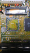
Well, the bottom and right side pads look OK. No need to mess with those I think. The problem area is up and left, especially upper left corner.
You can unmask the traces with sandpaper or, if you have one, a fiberglass pen. The pen allows to work on small areas and with some experience can be very precise.

Check the connections and vias that you had mapped previously, that didn't go anywhere. In case you have a broken vias that look OK form outside. You can reconstruct the missing traces with thin copper wire but I would avoid drilling. Just try to solder both ends and maybe, after you confirm the connection and spacing is good, put some glue on the ends.

To resolder the chip it might be best to remove the excess solder from the pads with some solder wick - but be careful, to much temperature and the solder pad will unglue itself, to little and the solder wick will stick to pad and rip it off when you try to move it. Use plenty of flux for such job (and just clean it later) and always move the copper braid along the traces/pads, not from the side. Soldering iron with good temperature control is the best tool for this.

Reply 82 of 98, by jnemo2004

User metadata
Rank Member
Rank
Member

Hello, good afternoon.
Some photos removing components:
1.- 8-bit ISA socket with hot air gun (600ºC). Some capacitors were also desoldered.
2.- Components desoldered one by one with a soldering iron. Two multilayer ceramic capacitors broken due to difficulty in removing them.

Now I am going to make a new sketch and apply the overkill solution of making a hole in the board to join back tracks to some pins of the IC.

This will take me a while.
Regards.

Attachments

  • 1.jpg
    Filename
    1.jpg
    File size
    210.39 KiB
    Views
    473 views
    File license
    Public domain
  • 2.jpg
    Filename
    2.jpg
    File size
    195.26 KiB
    Views
    473 views
    File license
    Public domain
  • 3.jpg
    Filename
    3.jpg
    File size
    45.73 KiB
    Views
    473 views
    File license
    Public domain
  • 4.jpg
    Filename
    4.jpg
    File size
    168.04 KiB
    Views
    473 views
    File license
    Public domain
  • 5.jpg
    Filename
    5.jpg
    File size
    165.01 KiB
    Views
    473 views
    File license
    Public domain

Reply 83 of 98, by PD2JK

User metadata
Rank Oldbie
Rank
Oldbie

Great job, looks clean. But those missing pads and traces.... That requires some skill which is way out of my league. 😁 Good luck and keep it up!

i386 16 ⇒ i486 DX4 100 ⇒ Pentium MMX 200 ⇒ Athlon Orion 700 | TB 1000 ⇒ AthlonXP 1700+ ⇒ Opteron 165 ⇒ Dual Opteron 856

Reply 85 of 98, by Nexxen

User metadata
Rank Oldbie
Rank
Oldbie
jnemo2004 wrote on 2024-03-20, 15:09:

This is difficult for me and I do not have the appropriate means or sufficient experience. I will try to do the best I can. In Spain we say that you can't make an omelet without breaking eggs.

No, it's not that difficult.
I did it and it was just a matter of patience.

Here's the thread:
ABC COMPUTER COMPANY, LTD. A3286 / A3886-01 V3.0 - repair thread (completed - just a few minor things left)

A better approach is to flatten the wires in order to have a flush surface to solder the chip, looking like pads. In my case I had a chip with leads (legs) and could easily make them stay at a higher angle (resting on the wire).
Don't let them loose, anchor the rebuilt pads with some solder mask. Make them a little longer sticking outward.

The thin wires that are in our braided electrical wires are good enough, mind they will conduct electricity and have to put solder mask.

Good luck.

P.s. lately someone posted his work and was far better than mine but I couldn't find it.

PC#1 Pentium 233 MMX - 98SE
PC#2 PIII-1Ghz - 98SE/W2K

Reply 86 of 98, by Thermalwrong

User metadata
Rank Oldbie
Rank
Oldbie

That's some clean removal 😀
Looks like you've still got some work to do and that'll be tricky without datasheets but just reconnecting the wires how they look like they should go should work. I've had a similar experience getting my oldest 386 motherboard working - your tracing prior to pulling the chip looks nice and clear.

I did something similar with a PLCC RAMDAC on a 3dfx card with a similar pin pitch & size - Re: What retro activity did you get up to today?
Thin metal legs from cut resistor / capacitor legs were used to remake the traces. The J-shaped legs on the PLCC that had those re-made traces were pushed up into the chip to let the chip sit level with the remaining pads. That's why the chip has a bunch of pencil marks on it to indicate which pins needed pushing up.

Reply 87 of 98, by Nexxen

User metadata
Rank Oldbie
Rank
Oldbie

@Thermalwrong: it makes happy to see a good restoration. 😀

I guess he is now convinced enough he can pull through this.

PC#1 Pentium 233 MMX - 98SE
PC#2 PIII-1Ghz - 98SE/W2K

Reply 88 of 98, by jnemo2004

User metadata
Rank Member
Rank
Member

Let me think about. First of all I have to prepare a new drawing. I am not able to work w/o a drawing/sketch.
Today, I just have ordered low temperature (138ºC) solder wire to solde the IC.
Thank you and regards.

Attachments

Reply 89 of 98, by Nexxen

User metadata
Rank Oldbie
Rank
Oldbie
jnemo2004 wrote on 2024-03-21, 12:33:

Let me think about. First of all I have to prepare a new drawing. I am not able to work w/o a drawing/sketch.
Today, I just have ordered low temperature (138ºC) solder wire to solde the IC.
Thank you and regards.

As you are at it, but some solder paste. Same temp.
It's super handy in many situations.

https://www.youtube.com/watch?v=HGElbkPBtuU

PC#1 Pentium 233 MMX - 98SE
PC#2 PIII-1Ghz - 98SE/W2K

Reply 90 of 98, by rasz_pl

User metadata
Rank l33t
Rank
l33t
jnemo2004 wrote on 2024-03-21, 12:33:

Today, I just have ordered low temperature (138ºC) solder wire to solde the IC.

this is bad, dont do that
- low melt solder is only used for Desoldering in special circumstances and requires through cleaning before reusing part/pcb again
- its connectivity is orders of magnitude worse than normal solder
- its brittle and weak, alloying and embrittlement of some metals (alu)
- mixed with ordinary lead solder melting point goes even lower
- with time it degrades solder connections near it
- its Chinese who knows what, no brand, no chemical composition, you dont even know if you are buying Bismuth, Indium or some industrial waste product

Open Source AT&T Globalyst/NCR/FIC 486-GAC-2 proprietary Cache Module reproduction

Reply 91 of 98, by jnemo2004

User metadata
Rank Member
Rank
Member

I will investigate this solution also. Thank you very much.

Nexxen wrote on 2024-03-21, 14:04:
As you are at it, but some solder paste. Same temp. It's super handy in many situations. […]
Show full quote
jnemo2004 wrote on 2024-03-21, 12:33:

Let me think about. First of all I have to prepare a new drawing. I am not able to work w/o a drawing/sketch.
Today, I just have ordered low temperature (138ºC) solder wire to solde the IC.
Thank you and regards.

As you are at it, but some solder paste. Same temp.
It's super handy in many situations.

https://www.youtube.com/watch?v=HGElbkPBtuU

Reply 92 of 98, by jnemo2004

User metadata
Rank Member
Rank
Member

I will do a test with the chinese solder wire before to use it.
Thank you very much.

rasz_pl wrote on 2024-03-21, 17:14:
this is bad, dont do that - low melt solder is only used for Desoldering in special circumstances and requires through cleaning […]
Show full quote
jnemo2004 wrote on 2024-03-21, 12:33:

Today, I just have ordered low temperature (138ºC) solder wire to solde the IC.

this is bad, dont do that
- low melt solder is only used for Desoldering in special circumstances and requires through cleaning before reusing part/pcb again
- its connectivity is orders of magnitude worse than normal solder
- its brittle and weak, alloying and embrittlement of some metals (alu)
- mixed with ordinary lead solder melting point goes even lower
- with time it degrades solder connections near it
- its Chinese who knows what, no brand, no chemical composition, you dont even know if you are buying Bismuth, Indium or some industrial waste product

Reply 93 of 98, by kingcake

User metadata
Rank Oldbie
Rank
Oldbie
jnemo2004 wrote on 2024-03-21, 12:33:

Let me think about. First of all I have to prepare a new drawing. I am not able to work w/o a drawing/sketch.
Today, I just have ordered low temperature (138ºC) solder wire to solde the IC.
Thank you and regards.

This is pretty high temp to be considered "low melt". Low melt is usually 58-85 degrees celsius. But, as others have said, do not use low melt for soldering. It will make very brittle joints. Only for removing chips, then you must tin and wick the pads several times to get as much low melt removed as possible. If you don't get most of the low melt off, you can tell your joints will look weird. Dull and gritty.

Reply 94 of 98, by jnemo2004

User metadata
Rank Member
Rank
Member

Hello good morning.
I am sure that all those who have advised me not to use this welding wire are right.
In my case, I buy practically everything on Aliexpress because the same tools purchased in the West are much more expensive. For this reason, sometimes you have to try things even if the results are not as excellent as using other means.
It must be taken into account that this board is not functional since the owner removed the IC to try to repair the board since he thought that the problem could be in the IC (or under the IC).
I just want to make a repair as easy as possible for me and go back to the situation before removing the IC W83C201P to try to get the motherboard working with your advice.
According to the information on this soldering wire, it does not contain lead (Sn42/Bi50/Cu8%).
Thank you very much for your help.

Reply 95 of 98, by kingcake

User metadata
Rank Oldbie
Rank
Oldbie
jnemo2004 wrote on 2024-03-23, 07:18:

According to the information on this soldering wire, it does not contain lead (Sn42/Bi50/Cu8%).
Thank you very much for your help.

Bi is Bismuth. Which is used to lower the melting temp of solder alloys. It should not be used as normal solder. It is extremely brittle.

Reply 96 of 98, by rasz_pl

User metadata
Rank l33t
Rank
l33t
jnemo2004 wrote on 2024-03-23, 07:18:

According to the information on this soldering wire, it does not contain lead (Sn42/Bi50/Cu8%).

Lead was never the problem, Bismuth is. It makes bad connections. Its not supposed to be used to make connections, its main purpose is desoldering.

Open Source AT&T Globalyst/NCR/FIC 486-GAC-2 proprietary Cache Module reproduction

Reply 97 of 98, by Deunan

User metadata
Rank Oldbie
Rank
Oldbie

There are soldering alloys with bismuth, exactly because it lowers the melting temperature. These are specialized (and expensive) wires/paste to be used in situations where typical soldering temperature (esp. if lead-free) would damage/destroy something that is not heat resistant. It's not brittle but it is dull and a pain to rework it later, if necessary, because it doesn't flow the same way as normal solder does, and adding flux doesn't help a whole lot. It might have worse mechanical properties but this mobo is not going on a missile that will pull 9G+ while maneuvering.

Can it be used for soldering the chip back? Sure. Would I use it in this case? No. But I do have some experience soldering and desoldering stuff and I probably have better tools for that as well. If the idea is to solder the trace fixing wires with standard solder, and then put the chip on with low-temperature one, then I'd say it's pretty good approach for someone not confident in their soldering abilities. This does lessen the risk of undoing the wire repair while soldering the chip back, although I would probably pick glue over this method.

Reply 98 of 98, by jnemo2004

User metadata
Rank Member
Rank
Member

Thank you very much.

Deunan wrote on 2024-03-23, 19:07:

There are soldering alloys with bismuth, exactly because it lowers the melting temperature. These are specialized (and expensive) wires/paste to be used in situations where typical soldering temperature (esp. if lead-free) would damage/destroy something that is not heat resistant. It's not brittle but it is dull and a pain to rework it later, if necessary, because it doesn't flow the same way as normal solder does, and adding flux doesn't help a whole lot. It might have worse mechanical properties but this mobo is not going on a missile that will pull 9G+ while maneuvering.

Can it be used for soldering the chip back? Sure. Would I use it in this case? No. But I do have some experience soldering and desoldering stuff and I probably have better tools for that as well. If the idea is to solder the trace fixing wires with standard solder, and then put the chip on with low-temperature one, then I'd say it's pretty good approach for someone not confident in their soldering abilities. This does lessen the risk of undoing the wire repair while soldering the chip back, although I would probably pick glue over this method.