VOGONS


First post, by froller

User metadata
Rank Member
Rank
Member

I've got network card on National Semiconductor AT/LANTIC DP83905 chip.
I configured it with the tool found on the Internet and added 32kB boot ROM at address 0xC800 but it turned into "Offboard checksum error" while booting my 386DX.
In a 486 board it can still be configured but same tool reports failed EPROM test. It also seems it doesn't save boot ROM settings to EPROM.
Switching boot ROM off with the same tool doesn't help.

I suspect wrong configuration tool. If someone have similar card could you please share the EPROM (chip in a red frame) dump and configuration tool for DOS.

ATLANTIC.jpg
Filename
ATLANTIC.jpg
File size
1.59 MiB
Views
566 views
File comment
DP83905
File license
Public domain

▓▓▓▓▓▓▓▓▓▓▓▓▓▓▓▓▓▓▓▓▓▓▓▓▓▓▓▓▓▓▓▓▓▓▓▓▓▓▓▓▓▓▓▓▓▓▓▓▓▓▓▓ 100%
Virus check complete. All viruses are working properly.

Reply 1 of 18, by Deunan

User metadata
Rank Oldbie
Rank
Oldbie

I've had some of those EEPROM chips die on network cards. Anything from glitches, to not being able to write anymore, to completly dead chip. Not sure why but various datasheets show a lot of chip revisions - my guess it the design was far from perfect and these do actually age and die on their own.
If you have a programmer you should look for a new/NOS 93C06 and program it with the values of the old one. Even if some data is glitched the config program might be able to re-write and correct it. I'm not sure if you can just swap the EEPROM with an empty one though - on cards I've dealt with (3Com) the ETH MAC is stored in there, along with the card PCB configuration (what ports are present, etc). So empty chip won't work, probably - a programmer is needed.

Eventually I was able to figure out how the checksum is calculated (by changing some config settings and re-reading the chip) so now I can create these for some cards from nothing, with custom MAC. But I'm pretty sure this one will have it implemented differently...

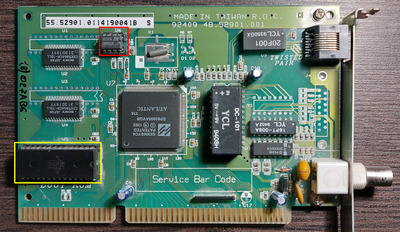
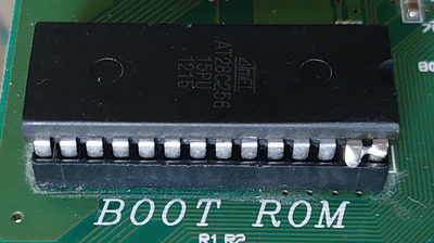
As for the config tool being wrong - I had some issues with the software too. 3com will try to validate the BOOT ROM in order to enable it so make sure to disable shadowing in mobo BIOS for that area. Realtek software would not work on 286 at all, and would glitch or hang on 486DLC type CPUs. Also, make sure to enable software protection on that 28C256 after programming, because some chips will try to toggle the high address lines, and this chip has /WE instead of A14 on pin 27, you might be getting instant corruption of the data once installed in the network card. This too would cause checksum error.

Reply 2 of 18, by froller

User metadata
Rank Member
Rank
Member

Nope, EEPROM is alive. I've found docs on this chipset and managed to reconstruct EEPROM content to the level it doesn't complain on "Off board parity error".
Will post the dump here as soon as I figure out what was the reason of corrupt config in EEPROM.

▓▓▓▓▓▓▓▓▓▓▓▓▓▓▓▓▓▓▓▓▓▓▓▓▓▓▓▓▓▓▓▓▓▓▓▓▓▓▓▓▓▓▓▓▓▓▓▓▓▓▓▓ 100%
Virus check complete. All viruses are working properly.

Reply 3 of 18, by froller

User metadata
Rank Member
Rank
Member

According to Hardware Users' Guide the configuration tool writes wrong values to Config C register.
That leads to incorrect mapping of boot ROM to address space and crashes on some old BIOSes.
I'm intentionnaly not placing here the config tool to avoid confusing other users.

Attachments

  • Filename
    ST93C06B1.zip
    File size
    182 Bytes
    Downloads
    7 downloads
    File comment
    Working dump of config EEPROM
    File license
    Public domain
  • Filename
    AN-897.pdf
    File size
    279.9 KiB
    Downloads
    13 downloads
    File comment
    DP83905EB-AT AT/LANTIC™ Hardware Users’ Guide
    File license
    Public domain

▓▓▓▓▓▓▓▓▓▓▓▓▓▓▓▓▓▓▓▓▓▓▓▓▓▓▓▓▓▓▓▓▓▓▓▓▓▓▓▓▓▓▓▓▓▓▓▓▓▓▓▓ 100%
Virus check complete. All viruses are working properly.

Reply 4 of 18, by Deunan

User metadata
Rank Oldbie
Rank
Oldbie

Not much in that EEPROM. BTW I see in the doc that the last cell should have value 0x73 on bits 15:8, and you have 0x00 in there. This is apparently just for future expansion though, which is not going to happen on this card I guess 😀

I wonder if the config tool itself is damaged. Glitched by bad RAM or damaged by virus maybe? Or for some reason the writing to EEPROM is not timed correctly, perhaps due to a bug that only manifests on some (faster) CPUs? What machine did you use to write the config to the card?

Reply 5 of 18, by froller

User metadata
Rank Member
Rank
Member

I use either 386DX-40 or 486x5-133. Same results except 486 doesn't complain about "Off board checksum"
I checked the contents of EEPROM each time ran configuration utility.
0x73 or 0x00 it doesn't seem to matter at least for my card.
It uses 8 first bytes to store MAC address and its checksum (my one had lower 2 bytes zeroed out so I added random number and updated the checksum) and 3 of last 4 bytes to store control register initial values.

It looks like I use wrong configuration tool. May be there're several revisions of DP83905 with different letters at the end.

▓▓▓▓▓▓▓▓▓▓▓▓▓▓▓▓▓▓▓▓▓▓▓▓▓▓▓▓▓▓▓▓▓▓▓▓▓▓▓▓▓▓▓▓▓▓▓▓▓▓▓▓ 100%
Virus check complete. All viruses are working properly.

Reply 6 of 18, by Deunan

User metadata
Rank Oldbie
Rank
Oldbie

The only photos I found indeed have different PCB layout (so there are at least 3 revisions) but all of them have DP83905AVQB chip on them.

I don't really have any other ideas, maybe try removing all the dust from the card (I use a small wall paiting brush with natural hair for that, when it gets dirty it can be cleaned with water and soap and dried). Dust can attract moisutre and other dirt particles, this can in theory lead to some current leakage between dense chip pins. I don't think it's the case here but it won't hurt to clean the card.

Reply 7 of 18, by froller

User metadata
Rank Member
Rank
Member

Well... I partially figured out the problem. And it is not related to configuration tool but to the card itself.
My card is damn slow and refuses to work properly at higher bus frequencies or ROMs I use (AT28C64B and AT28C256) are too slow. That is why it caused checksum errors.

Moreover it acts pretty strange even at lower clock.
When I set boot ROM address equal to multiple of 0x800 it loads garbage. However if I set boot ROM address as N * 0x800 + 0x400 it shows ROM content correctly. At least first kilobyte.
This got me thinking of A14 floating or pulled high.

AT28C256 is always read as garbage. I've checked the board and found it have A14 of ROM tied to +5V. So and only higher 16k can be accessed.
AT28C64B works only mapped to addresses with bit 14 set probably for the same reason.

The more I dive into it the more questions I got to the one who designed this NIC. 😠

▓▓▓▓▓▓▓▓▓▓▓▓▓▓▓▓▓▓▓▓▓▓▓▓▓▓▓▓▓▓▓▓▓▓▓▓▓▓▓▓▓▓▓▓▓▓▓▓▓▓▓▓ 100%
Virus check complete. All viruses are working properly.

Reply 8 of 18, by Deunan

User metadata
Rank Oldbie
Rank
Oldbie
froller wrote on 2024-02-16, 01:37:

AT28C256 is always read as garbage. I've checked the board and found it have A14 of ROM tied to +5V. So and only higher 16k can be accessed.

Just a quick question, do you mean 28C256 pinout or standard 27256 pinout? Because these two are different and A14 on the EEPROM is on pin 1, which on standard ROM/EPROM is VPP, so would be permanently tied to +5V.

Reply 9 of 18, by froller

User metadata
Rank Member
Rank
Member
Deunan wrote on 2024-02-16, 09:48:

Just a quick question, do you mean 28C256 pinout or standard 27256 pinout? Because these two are different and A14 on the EEPROM is on pin 1, which on standard ROM/EPROM is VPP, so would be permanently tied to +5V.

I mean AT28C256 @ DIP-28.
The card looks too ancient for 28-series EEPROMs.

▓▓▓▓▓▓▓▓▓▓▓▓▓▓▓▓▓▓▓▓▓▓▓▓▓▓▓▓▓▓▓▓▓▓▓▓▓▓▓▓▓▓▓▓▓▓▓▓▓▓▓▓ 100%
Virus check complete. All viruses are working properly.

Reply 10 of 18, by Deunan

User metadata
Rank Oldbie
Rank
Oldbie

In that case, unless you need 32k of code space, just assume that A14 is going to be high all the time and either program the upper half of the EEPROM, or just put in the image twice. In the latter case you can even have 2 different 16k images in there if you bend the pin 1 of the chip so it does not go into socket, and instead solder a wire to GND or +5V to select which half is to be addressed.

Just make sure to enable the software write protection I mentioned earlier, and avoid non-B 28C64 which lacks this feature. I've used 28C256 on network cards and it worked fine. The only problem is cards/mobos that require full 32k of space for BIOS and in that case it's better to use EPROM emulator part like 27E512 than mess around with wires and pins that don't match the original pinout.

Reply 11 of 18, by froller

User metadata
Rank Member
Rank
Member
Deunan wrote on 2024-02-16, 14:38:

Just make sure to enable the software write protection I mentioned earlier, and avoid non-B 28C64 which lacks this feature.

Yes, I've already faced the problem with EEPROM contents corruption. No matter if I set BPWR (DP83905 Control B register bit 6) or not it rewrites random bytes. So write protection is crucial.
Looks like the card was designed without 28-series 5V EEPROMs in mind. So only 12V or UV-erasable chips are expected to be used.

▓▓▓▓▓▓▓▓▓▓▓▓▓▓▓▓▓▓▓▓▓▓▓▓▓▓▓▓▓▓▓▓▓▓▓▓▓▓▓▓▓▓▓▓▓▓▓▓▓▓▓▓ 100%
Virus check complete. All viruses are working properly.

Reply 13 of 18, by froller

User metadata
Rank Member
Rank
Member
rasz_pl wrote on 2024-02-16, 18:02:

how about bending WE pin up?

This probably should help. But I'd also tied it to Vcc just to make sure it never going to be active.

It's more interesting what to do with A14 of ROM chip. I've placed 2 copies of XT_IDE at offset 0x0000 and 0x4000, bent up pin 1 (A14) and even pulled it low. It doesn't change a thing. Boot ROM keeps being mapped to (2 * N + 1) * 0x400

▓▓▓▓▓▓▓▓▓▓▓▓▓▓▓▓▓▓▓▓▓▓▓▓▓▓▓▓▓▓▓▓▓▓▓▓▓▓▓▓▓▓▓▓▓▓▓▓▓▓▓▓ 100%
Virus check complete. All viruses are working properly.

Reply 14 of 18, by froller

User metadata
Rank Member
Rank
Member

So the crime was solved.
Particular card does support only 27-series EPROMs up to 27C256. Maximum boot ROM size is 32kB.
Pin 27 (\WE) of EPROM is connected directly to A14 line in ISA slot. So addresses with A14 low makes 28-series EPROM to switch data bus for input leaving no active outputs on data bus. That leads to garbage read from data bus.
So as Deunan mentioned corrupting of EPROM content is caused by A14 line interferring with \WE pin.

For 28-series EPROM to work it's necessary to disconnect A14 line of EPROM from ISA and tie it to +5V. And for 28C256 you also have to place boot code into upper 16kB. You probably will have ghost copy of boot ROM but it gonna work.

20240222_133856.jpg
Filename
20240222_133856.jpg
File size
708.61 KiB
Views
245 views
File comment
AT28C256 EEPROM with broken pin 26 converted to ROM
File license
Public domain

▓▓▓▓▓▓▓▓▓▓▓▓▓▓▓▓▓▓▓▓▓▓▓▓▓▓▓▓▓▓▓▓▓▓▓▓▓▓▓▓▓▓▓▓▓▓▓▓▓▓▓▓ 100%
Virus check complete. All viruses are working properly.

Reply 15 of 18, by Deunan

User metadata
Rank Oldbie
Rank
Oldbie
froller wrote on 2024-02-22, 11:27:

For 28-series EPROM to work it's necessary to disconnect A14 line of EPROM from ISA and tie it to +5V.

This shouldn't be needed on 28C256. In the datasheet look for "Software Data Protection". Not sure what EEPROM programmer you have but most should be capable of turning this option on/off. When it's on the /WE pin will not cause a write unless you follow a specific unlock procedure, which is extremly unlikely to happen at random during normal operation. It's a bit like with Flash chips. This should prevent any corruption on 28C256 and 28C64B parts, but non-B 28C64 does not have this feature and bending the pin is the only way. Or picking a card that guarantees the unsused high address lines will not toggle (like Realtek 8019) but that obviously will limit the binary image size in the EEPROM.

As for the +5V on pin 1, yes that will require putting the image into upper half of the EEPROM. Or use an "EPROM emulator" part like W27E512 or SST27SF512 - these are Flash based but have pinout identical to normal 27xxx EPROMs and can't be written to or ereased without +12V present, so any combination of 5V signals is always safe. The only drawback is the price these days, or you can buy some Chinese offering - often used but still working. Do note these parts have limited amount of erase cycles, sometimes as low as 100. That doesn't mean 101 will fail but with frequend use they will degrade much faster than EEPROM.

Reply 16 of 18, by froller

User metadata
Rank Member
Rank
Member
Deunan wrote on 2024-02-22, 14:00:

This shouldn't be needed on 28C256. In the datasheet look for "Software Data Protection". Not sure what EEPROM programmer you have but most should be capable of turning this option on/off. When it's on the /WE pin will not cause a write unless you follow a specific unlock procedure, which is extremly unlikely to happen at random during normal operation. It's a bit like with Flash chips. This should prevent any corruption on 28C256 and 28C64B parts, but non-B 28C64 does not have this feature and bending the pin is the only way.

I use TL866 programmer and it is capable of enabling write protection on AT28C256 and AT28C64B. And write protection in deed helps to keep content of EEPROM safe but it is not enough.

The issue is in incorrect Memory Support Data Bus (intrinsic data bus of the card, see datasheet on DP83905) operation.
When both \WE and \CE go low AT28Cxxx disconnects its internal output buffers from data pins and starts to read from them instead of writing. Even if no write operation can be performed due to W/P it is still waiting for control sequence (eg. W/P disabling).
In that case we have AT28C256 and DP83905 both reading from Memory Support Data Bus and no one writing to it.
On both ends of MSDB we have only inputs connected and this renders MSDB data lines floating. So DP83905 reads whatever garbage it picks from the air.

And this can be clearly seen with dumping system memory with debug command. If the card had pull-up resistors on MSDB then we'd see all 0xFF's but it isn't and we see garbage.

BTW that poor AT28C256 had pin 27 broken long before. So no EEPROMs were harmed. 😀

▓▓▓▓▓▓▓▓▓▓▓▓▓▓▓▓▓▓▓▓▓▓▓▓▓▓▓▓▓▓▓▓▓▓▓▓▓▓▓▓▓▓▓▓▓▓▓▓▓▓▓▓ 100%
Virus check complete. All viruses are working properly.

Reply 17 of 18, by Deunan

User metadata
Rank Oldbie
Rank
Oldbie
froller wrote on 2024-02-22, 15:28:

When both \WE and \CE go low AT28Cxxx disconnects its internal output buffers from data pins and starts to read from them instead of writing.

Right, I didn't consider that. That means the /WE pin on the EEPROM must not be driven low if you need valid ouput for A14=0 (without messing about with the pinout).
In my defence I stopped using those EEPROMs once I got burned by the different pinout, I now stick to "EPROM emulator" parts, and actual EPROMs once I'm happy with the result. Last time I did use 28C256 I needed less than 16k of space on it so I just mapped it to the upper half when A14=1 and it worked fine for my purposes.

Reply 18 of 18, by froller

User metadata
Rank Member
Rank
Member
Deunan wrote on 2024-02-22, 17:08:

In my defence I stopped using those EEPROMs once I got burned by the different pinout, I now stick to "EPROM emulator" parts, and actual EPROMs once I'm happy with the result.

I stuck with EEPROMs since the time I have not yet bought TL866 and used home brewed programmer made from Arduino Mega.
Now I'm waiting for 27-series UV EPROMs to be delivered.
It usually takes 2 to 3 weeks but this time they celebrate Chinese New Year and whole China seems to be off work. So happy New Year to them! 🥳

▓▓▓▓▓▓▓▓▓▓▓▓▓▓▓▓▓▓▓▓▓▓▓▓▓▓▓▓▓▓▓▓▓▓▓▓▓▓▓▓▓▓▓▓▓▓▓▓▓▓▓▓ 100%
Virus check complete. All viruses are working properly.