ubiq wrote on 2024-03-11, 03:26:
Took a break on this one for a few days. 😅
Hey no worries.
This is actually a more effective way to troubleshoot stuff, since it allows you to think problems through in the back of your head. 😀
Also, I myself will be traveling a little this week and might not able to reply for a few days.
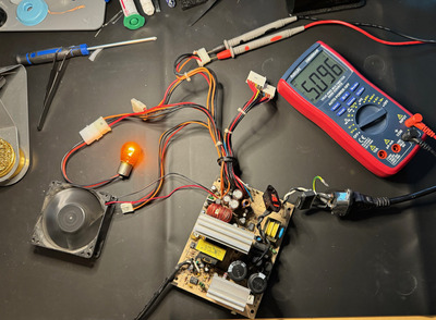
The green resistor may or may not be an inductor (most likely not, though.) What does the PCB designator say? If it's R-something, it's a resistor. And if it's L-something, then it's inductor. You can also verify if the resistance you measured across it corresponds to the color codes (probably going to be a 25 Ohm if it is a resistor.) If it's an inductor, it should show very low resistance.
ubiq wrote on 2024-03-11, 03:26:
Looked at the optocouplers - a little googling told me I can only test the LED side with a multimeter alone, but they seemed fine.
The output / driver side of the optocouplers can be tested too, but it's a bit tricky.
An optocoupler taken out of circuit should show open-circuit on the output / driver side.
Now, if you have a spare 470 - 1000 (1K) Ohm resistor, you can wire that in series with the input / LED side and connect this series circuit to a battery. This should drive the LED to turn On, which in turn should make the output / driver side resistance become low/lower. Of course, this test is another one that only works with the opto out of circuit.
ubiq wrote on 2024-03-11, 03:26:
Haven’t found any resistors or diodes on the board that seem to test bad.
Perhaps remove and test the caps on the output. I suspect they will be fine. But perhaps in the off-chance one of them has a broken lead or something more crazy / exotic like that. After all, if you have never had the PSU working and you don't have any history of what happened to it, there's no telling what could have caused the problem. So in such cases, you just have to keep your eyes and mind open before ruling anything out. Most likely, it will probably be something very simple that we either overlooked or didn't see. PSUs like these generally don't have issues.
I have a few more tests up my sleeves. I'll put more details when I get back... that is, if you're still interested to continue. I don't want to be pushing by any means. But if you're enjoying this, we can keep going.
These will involve voltage injection. So in the mean time, see if you have a 5V and a 12V power adapter, each rated anywhere from 0.75 to 3 Amps should do. Also a non-grounded (2-pin wall plug) adapter than can do more than 16V but less than 30V (ideally less than 24V).
ubiq wrote on 2024-03-11, 03:26:
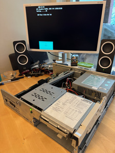
Anyway, I put everything back where it should be and made sure it was still broken in the same way, and yes - I haven’t managed to break it any further, so that’s something.
That's always good. 😀