VOGONS


First post, by boby

User metadata
Rank Member
Rank
Member

So, I hope someone remembers my first post [SOLVED] Keyboard + mouse connectors problem, where I had a keyboard problem.
Now, I have the same error again. This time I checked all the traces and volteges and all seams correct, so the problem must be somewhere else.
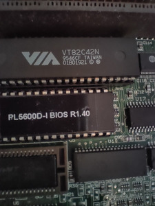
What I noticed is that my kb controller shows +5V on many pins. Is there maybe schematic for this piece so I can compare?
It is cheep to replace but would like to test it first.

Update1: Not many, but almost all pins on one side of the chip shows 5V. That can't be correct?

Attachments

Last edited by boby on 2024-03-07, 19:01. Edited 1 time in total.

Reply 1 of 8, by rasz_pl

User metadata
Rank l33t
Rank
l33t

melted connector last time got loose inside?
which pins are constantly at 5V? and are they shorted to 5V power rail (resistance measurement with system off)?

Open Source AT&T Globalyst/NCR/FIC 486-GAC-2 proprietary Cache Module reproduction

Reply 2 of 8, by boby

User metadata
Rank Member
Rank
Member
rasz_pl wrote on 2024-03-02, 13:20:

melted connector last time got loose inside?

Connector looks fine.

rasz_pl wrote on 2024-03-02, 13:20:

which pins are constantly at 5V? and are they shorted to 5V power rail (resistance measurement with system off)?

Almost all on the top side, of the image I posted. Not sure that I understood what to measure? But, it can't be that all pins are powered with voltage.

Reply 3 of 8, by snufkin

User metadata
Rank Oldbie
Rank
Oldbie

There's a difference between a pin being directly connected/shorted to +5, or pulled up to +5 via a resistor. A pull up resistor means that if the pin isn't being actively driven by the chip then it'll measure at +5V, but the chip can drive the pin to Gnd. For example, on the PS/2 connector, one pin is directly connected to Gnd, one to +5V and 2 pins (clock and data) are pulled up to +5V. So the Clock, Data and power pins will all measure as +5V when no data is being transmitted, but only the power pin is directly connected to +5.

A way to check is to turn the board off and measure resistance between each pin and a known +5 point (easiest on the power connector). I'd guess that one or two will measure 0 ohms, but others something like 1k - 10k. At the same time it's probably worth checking your PS/2 connector and measuring the resistance to +5 of the clock, data and power pins, and resistance to Gnd of the ground pin.

Reply 4 of 8, by boby

User metadata
Rank Member
Rank
Member
snufkin wrote on 2024-03-02, 19:06:

There's a difference between a pin being directly connected/shorted to +5, or pulled up to +5 via a resistor. A pull up resistor means that if the pin isn't being actively driven by the chip then it'll measure at +5V, but the chip can drive the pin to Gnd. For example, on the PS/2 connector, one pin is directly connected to Gnd, one to +5V and 2 pins (clock and data) are pulled up to +5V. So the Clock, Data and power pins will all measure as +5V when no data is being transmitted, but only the power pin is directly connected to +5.
A way to check is to turn the board off and measure resistance between each pin and a known +5 point (easiest on the power connector). I'd guess that one or two will measure 0 ohms, but others something like 1k - 10k.
At the same time it's probably worth checking your PS/2 connector and measuring the resistance to +5 of the clock, data and power pins, and resistance to Gnd of the ground pin.

PS/2:

Ground vs Data Pin = infinite -> this is strange?
Ground vs Ground Pin = 0 Ohm
Ground vs Power Pin = 8.61 kOhm
Ground vs Clock Pin = 9.38 kOhm

Update 1
Resistance on controller:
All pins are in range from around 1.3 kOhm till around 9.5 kOhm except:
Pin 4, pin 10 & pin 11, pins from 23 till pin 33 and pins from 37 till pin 40 have infinite resistance
Pin 8 = 15 kOhm

Update 2:
I didn't measure data pin correctly on PS/2 connector first time. It is ok, it's not infinite resistance, but around 9.61 kOhm. I was measuring not connected pin. Stupid me.
This means that the PS/2 connector is fine, I guess, but I would like someone to confirm it.

Last edited by boby on 2024-03-03, 19:28. Edited 1 time in total.

Reply 7 of 8, by rasz_pl

User metadata
Rank l33t
Rank
l33t
boby wrote on 2024-03-03, 23:20:

Ok, narrowed down the problem. It is either connector again or keyboard cable. Because there is error again and moving the kb cable a bit fixes it. Will investigate further.

"melted connector last time got loose inside" 😀 When soldering connectors its very easy to slightly melt them inside by keeping soldering iron for too long on legs. Its invisible from the outside, but inside connector you no longer have snug fit. It can still be keyboard cable tho.

Open Source AT&T Globalyst/NCR/FIC 486-GAC-2 proprietary Cache Module reproduction

Reply 8 of 8, by boby

User metadata
Rank Member
Rank
Member
rasz_pl wrote on 2024-03-04, 01:58:
boby wrote on 2024-03-03, 23:20:

Ok, narrowed down the problem. It is either connector again or keyboard cable. Because there is error again and moving the kb cable a bit fixes it. Will investigate further.

"melted connector last time got loose inside" 😀 When soldering connectors its very easy to slightly melt them inside by keeping soldering iron for too long on legs. Its invisible from the outside, but inside connector you no longer have snug fit. It can still be keyboard cable tho.

It is the connector. Never cross my mind that I could damage it with iron.
I put some WD-40 and for now it works. Even if I move cable around, it doesn't
brake.