VOGONS


First post, by majestyk

User metadata
Rank Oldbie
Rank
Oldbie

I hope, some people here own this mainboard and can help me identify mainly the resistor values that are missing on the single CPU version.

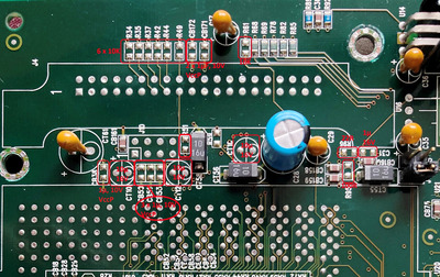
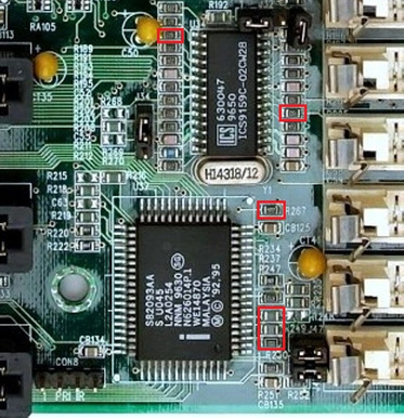
First there are some components missing near the VRM socket:

tyan_s1662_vrm.jpg
Filename
tyan_s1662_vrm.jpg
File size
314.87 KiB
Views
1001 views
File license
Public domain

R34, R35, R37, R42, R44, R49, CB171, CB172 and R61 are not populated. I haven´t found good pictures of this area so far, so I don´t know if all these components are present on the dual CPU version and I also need to know the resistor values.

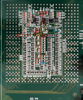
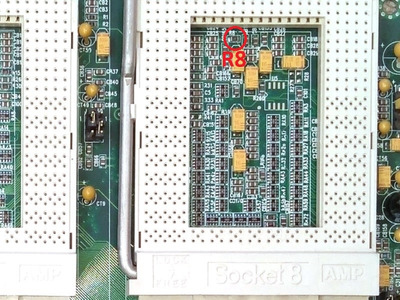
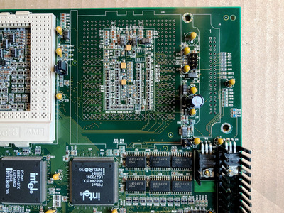
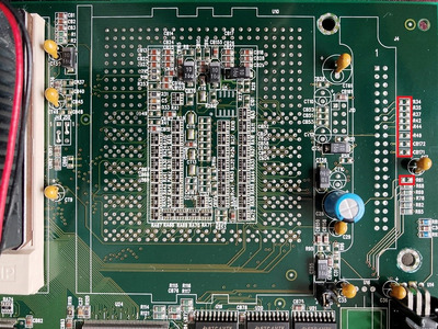
Next are the components inside the 2nd CPU socket:

tyan_s1662_cpu2.jpg
Filename
tyan_s1662_cpu2.jpg
File size
226.77 KiB
Views
1001 views
File license
Public domain

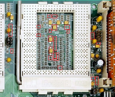
I need to know the values of the missing R257, CB49, R8, CB15, CB16, CB70, R27, R28, C101, R253, R254, CB167, CB170, CB168, CB169, C103, CB67, CB68, CB69 and the row CB52-CB5x-CB56-CB58-CB59-CB60-CB64.

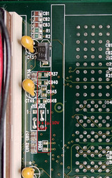
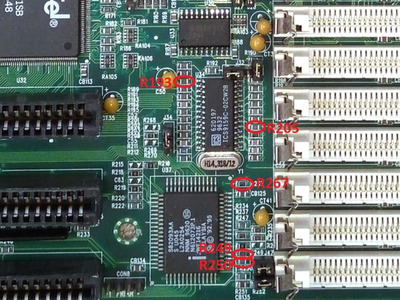
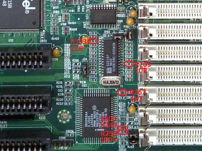
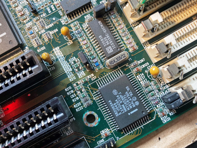
Finally(?) there are the components around the APIC chip:

tyan_s1662_apic.jpg
Filename
tyan_s1662_apic.jpg
File size
152.39 KiB
Views
1001 views
File license
Public domain

R247 -> 0R
R267, R249, R250 plus R193, R205 at the clock generator are missing. (I assume the APIC chip gets it´s own clock signal.)

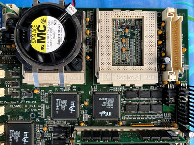
The V-I/O transistor and heatsink, the jumper headers, the 10µF radial- and SMD-tantalums, the ZIF- socket and VRM-socket are obvious 😀
But any help ID-ing these components, especially the resistors is highly appreciated, otherwise this project cannot be materialized!

Last edited by majestyk on 2024-03-29, 18:18. Edited 2 times in total.

Reply 2 of 30, by chinny22

User metadata
Rank l33t++
Rank
l33t++
luckybob wrote on 2024-03-11, 16:55:

here we go again...

yay. It's a crime to run a PPro all by itself.

Reply 3 of 30, by Sphere478

User metadata
Rank l33t++
Rank
l33t++

WORKING Shuttle HOT-613 (Single to Dual - Pentium Pro)

Here is a similar thread.

Also, my sig has a socket 7 conversion. Idk if they are much help.

Guess we will just have to wait for a dual owner to show up and take some readings/pics. For best results the in question components should probably be measured removed. Except those with visible markings that identify them.

In meantime, order the socket and apic.

Sphere's PCB projects.
-
Sphere’s socket 5/7 cpu collection.
-
SUCCESSFUL K6-2+ to K6-3+ Full Cache Enable Mod
-
Tyan S1564S to S1564D single to dual processor conversion (also s1563 and s1562)

Reply 5 of 30, by majestyk

User metadata
Rank Oldbie
Rank
Oldbie

I will start with some measuring to find out the connections between the caps and CPU pins. Those connected to V I/O and Vcc are probably all the same capacity like 100nF, I could remove one relating cap inside the 1st CPU socket and mesure it´s capacity.
There are also some components I have to order in the meantime (Intel APIC etc.).

If an owner of a dual socket version shows up, all that´s left to do is reading the printed values of the resistors with a good magnifying glass.

Reply 6 of 30, by luckybob

User metadata
Rank l33t
Rank
l33t
majestyk wrote on 2024-03-12, 06:40:

If an owner of a dual socket version shows up, all that´s left to do is reading the printed values of the resistors with a good magnifying glass.

A good idea, but most of them are not marked. I will try.

I'll have to unbox it when i get to my garage today.

It is a mistake to think you can solve any major problems just with potatoes.

Reply 7 of 30, by majestyk

User metadata
Rank Oldbie
Rank
Oldbie

That´s good news!
I´m sure the resistors are all marked. Most of them have a greenish/sage color and the white printing has minimal contrast. Good lighting and magnifying will do the trick...at least I hope so 😉

Reply 8 of 30, by majestyk

User metadata
Rank Oldbie
Rank
Oldbie

In the meantime I found the values of the components in the first picture around the VRM-socket:

tyan_s1662_vrm2a.jpg
Filename
tyan_s1662_vrm2a.jpg
File size
1.27 MiB
Views
707 views
File license
Fair use/fair dealing exception

I also found that R51 is a 10K pull-up resistor at the "Power Good" pin of the VRM socket (pin 9A).

Now it´s time to have a look at the missing caps inside the 2nd CPU socket.
Generally all positions marked "CBxyz" are between Vss and either VccP (core voltage), VccS (cache voltage 3.3V) or VccT (Termination voltage 1.5V).
Capacitors mamed "Cxyz" are between CPU pins.
Intel recommends 40 capacitors 1µF around ind inside the socket for filtering / stabilizing the core voltage VccP. I assume all the caps connected to VccP belong to this group.
The ceramic capacitors that are already present are for VccS and VccT.

tyan_s1662_vrm3a.jpg
Filename
tyan_s1662_vrm3a.jpg
File size
1.03 MiB
Views
674 views
File license
Fair use/fair dealing exception

R254 -> 220R
R253 -> 330R
R260 -> 10K
(Edit:) R257 -> 10K
What I still need to know are
R8

Between the CPU sockets there are just 5 caps for decoupling / filtering of VccP

tyan_s1662_vrm4a.jpg
Filename
tyan_s1662_vrm4a.jpg
File size
220 KiB
Views
668 views
File license
Fair use/fair dealing exception
Last edited by majestyk on 2024-03-29, 09:39. Edited 8 times in total.

Reply 9 of 30, by Sphere478

User metadata
Rank l33t++
Rank
l33t++

For the ones in the socket, could you not basically extrapolate based on cpu socket 1?

Sphere's PCB projects.
-
Sphere’s socket 5/7 cpu collection.
-
SUCCESSFUL K6-2+ to K6-3+ Full Cache Enable Mod
-
Tyan S1564S to S1564D single to dual processor conversion (also s1563 and s1562)

Reply 10 of 30, by majestyk

User metadata
Rank Oldbie
Rank
Oldbie

The layout inside CPU 1 is completely different. For determining the capacitors it was easier the way I did it.
But when it comes to the resistors, measuring at the respective resistors of CPU1 will be all that´s left - for the time being I hope luckybob can detect the printings on his board.

There are 6 resistors left that I cannot identify myself:
================================
= R8 (inside the 2nd CPU socket at the top) =
================================

ID_01.jpg
Filename
ID_01.jpg
File size
157.6 KiB
Views
609 views
File license
Public domain

================================
= R193, R205 (at the clock generator chip) =
= R267, R249, R250 (at the APIC chip) =
================================

ID_02.jpg
Filename
ID_02.jpg
File size
168.92 KiB
Views
609 views
File license
Public domain
Last edited by majestyk on 2024-03-15, 14:21. Edited 7 times in total.

Reply 11 of 30, by majestyk

User metadata
Rank Oldbie
Rank
Oldbie

Today I soldered most of the birdseed, as far as I had it on stock. The 2nd termination-voltage regulator got fitted in also.
Now waiting for the APIC chip to arrive. 2nd CPU socket and 2nd VRM socket will be added last.

tyan_s1662_stage1.jpg
Filename
tyan_s1662_stage1.jpg
File size
1.14 MiB
Views
601 views
File license
Fair use/fair dealing exception

Reply 12 of 30, by luckybob

User metadata
Rank l33t
Rank
l33t

Sorry, got distracted and completely forgot to snap some pics.

https://imgur.com/a/8FpSwmP

its amazing what pictures we can get with consumer grade cell phones.

It is a mistake to think you can solve any major problems just with potatoes.

Reply 14 of 30, by Sphere478

User metadata
Rank l33t++
Rank
l33t++

If not hosting images here, at least make a guide listing values and positions please 😀 here in 5-10 years those images are gonna be dead links

Sphere's PCB projects.
-
Sphere’s socket 5/7 cpu collection.
-
SUCCESSFUL K6-2+ to K6-3+ Full Cache Enable Mod
-
Tyan S1564S to S1564D single to dual processor conversion (also s1563 and s1562)

Reply 15 of 30, by luckybob

User metadata
Rank l33t
Rank
l33t

I mean, imgur has been around since like 2010. I'm not exactly worried. Also, I'm keeping the motherboard around, so if the image host goes down and someone else wants to do this, I'll be here to take new pics.

It is a mistake to think you can solve any major problems just with potatoes.

Reply 16 of 30, by majestyk

User metadata
Rank Oldbie
Rank
Oldbie

As opposed to what everybody believed in the beginning, today there´s amnesia on the net everywhere. Websites, FTP servers and tons of Microsoft knowledge base articles are disappearing as we speak.

To be on the safe side: R8 inside CPU-socket 2 has been idientified as 330R.
And here´s the completed APIC / clock generator area:

ID_02a.jpg
Filename
ID_02a.jpg
File size
169.95 KiB
Views
467 views
File license
Public domain

Reply 17 of 30, by majestyk

User metadata
Rank Oldbie
Rank
Oldbie

The only component still missing is the Intel APIC chip, that seems to be stuck at customs.
Meanwhile I added the 2nd socket, VRM connector and the missing caps and resistors.

tyan_s1662_2nd_socket.jpg
Filename
tyan_s1662_2nd_socket.jpg
File size
2 MiB
Views
364 views
File license
Fair use/fair dealing exception

Reply 18 of 30, by Sphere478

User metadata
Rank l33t++
Rank
l33t++

Should be able to fire it up with second cpu and do a smoke test at this point. Ohm out power rails make sure their resistance didn’t change much

A current limiter would be a good idea,

Sphere's PCB projects.
-
Sphere’s socket 5/7 cpu collection.
-
SUCCESSFUL K6-2+ to K6-3+ Full Cache Enable Mod
-
Tyan S1564S to S1564D single to dual processor conversion (also s1563 and s1562)

Reply 19 of 30, by majestyk

User metadata
Rank Oldbie
Rank
Oldbie
Sphere478 wrote on 2024-03-26, 18:02:

Should be able to fire it up with second cpu and do a smoke test at this point. Ohm out power rails make sure their resistance didn’t change much
A current limiter would be a good idea,

I tested the system a couple of times after adding components, checked for shorts etc. also. Last test was before I added the second CPU socket.

Yesterday the APIC chip arrived from a nice seller from Ukraine, so I could proceed.

After soldering the chip and doing some cleaning the system wouldn´t finish POST correctly in about 70% of the cases. Bending the PCP or pressing against the RAM sticks had an effect on the outcome.
So I seached for bad soldering joints and found about 10 of them at the legs of the chipset . Due to all that handling, bending and heating the board the solder junctions must have deteriorated. After finding all of them and resoldering the system started 100% reliable again.

Unfortunately the second CPU was not detected, it was detected occasionally at 2 or 3 starts out of 50.
I suspected flux remnants inside the new soldered CPU socket and cleaned it very carefully with IPA - to no avail.

While reviewing everything I had done, I noticed I skipped one resistor inside CPU socket #2: R257. I had even marked it in one of the first pictures, but then forgot it. It pulls pin "AA45" (PREQ#) up tu 3.3V. It´s a 10K resistor. Once it was added, everything´s working perfectly.
The board came with a BIOS from 1998, but reset doesn´t work with it (neither KB-shortcut nor switch), so I went back to V3.03 from Oct. 1996.

p6dne_apic.JPG
Filename
p6dne_apic.JPG
File size
1.56 MiB
Views
290 views
File license
Fair use/fair dealing exception
Last edited by majestyk on 2024-03-28, 18:27. Edited 1 time in total.