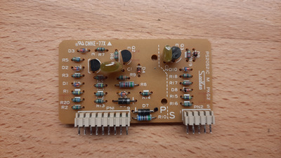
OK, using the above photo as a reference, the left-side column of pins is the primary side of the transformer. First and 2nd pin from the top are for the primary main winding. On the transformer itself, these two pins should measure pretty low resistance to each other and no resistance / continuity to any other pins. The 3rd, 4th, and 5th pin (last pin on bottom) are for the primary auxiliary winding and/or feedback winding. These three should show low resistance / continuity to each other when measuring the transformer, and no resistance / continuity to any other pins.
As for the column of pins on the right side - that's the secondary side. All of the pins, except possibly the last one on the bottom, should show continuity to each other.
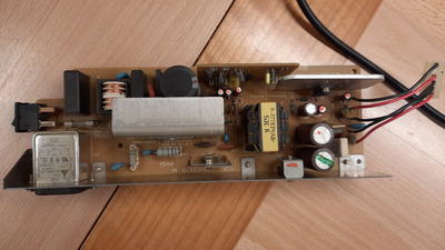
Doing some tracing, I believe the output rail pinout I suggested in my previous post is correct. So it's indeed 34V, Ground, Ground, 5V(?), and Activate/PS_ON(?)
By the way, be careful when handling the board, especially with the transformer removed - that large electrolytic cap on the primary could possibly remain charged up for a long time if there is no discharge path for it on the PCB. Depending on which part of the world you live it (i.e. country with 230V AC or 120V AC), the cap could have either up to 340V DC or 170V DC on its terminals. Discharge before doing any resistance measurements on the primary side of the PSU - both for your own and the safety of the multimeter. 😀