VOGONS


First post, by cross

User metadata
Rank Newbie
Rank
Newbie

Hello everyone.

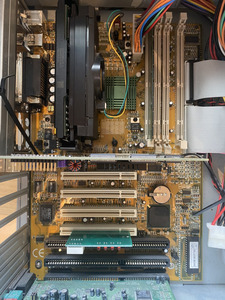
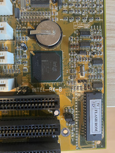
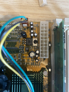
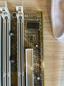
I recently pulled out a machine from storage to check on it a bit. P3 Machine with Full Yes INTEL 82440BX-S motherboard.
Noticed a weird issue that when the power is plugged in and PSU switched on, it looks like the standby voltage is "leaking" to various motherboard components.

So when the PSU is plugged in, I see that CPU fan is running (low speed), GPU fan running (low speed).
The same goes for plugging in a POST card in the PCI slot, the indicator leds on it is also lit, but dim. The same with the power LED on the front.

The machine power on and works as normal other than this.

It has been in storage for a while, I can not tell if it was like this before or something happened during storage.

The checks I have done so far is just to check that its not the PSU. It is behaving as normal, only supplying the VSB voltage until the PSON signal is present, where it starts up as normal.

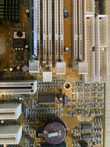
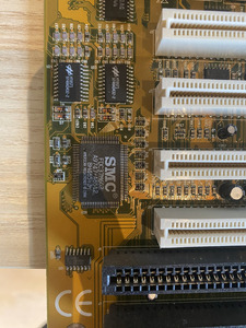
I include a image of the motherboard for reference.

Any ideas on what can be the issue causing this? Any assistance is greatly appreciated!

Attachments

  • p3board_ny.jpeg
    Filename
    p3board_ny.jpeg
    File size
    476.36 KiB
    Views
    793 views
    File license
    Fair use/fair dealing exception

Reply 1 of 30, by rasz_pl

User metadata
Rank l33t
Rank
l33t

I had a second look and its not BX-S after all https://theretroweb.com/motherboards/s/full-y … intel-82440bx-s
Its "Full Yes Intel BX-B", missing from https://theretroweb.com/motherboards/?manufac … 1&chipsetId=283 altogether.

Check if it still does it (lightly lit power led) with:
-everything unplugged from Front panel header (JP5?)?
-everything unplugged, all cards/cables, except cpu/ram/keyboard/atx supply?
-pulled out of the case?

+5vsb is connected to JP5? power button connector and suspend circuit. J21? JP21? Whatever is at the right of coin battery, those three 74xxx chips and jumper. Better pic so all parts are readable would be nice.

>The same goes for plugging in a POST card in the PCI slot, the indicator leds on it is also lit, but dim. The same with the power LED on the front.

some of those leds are powered straight from chipset

>CPU fan is running (low speed), GPU fan running (low speed).

and those are 12V, how would 5Vsb leak to 12V circuit?

>The checks I have done so far is just to check that its not the PSU. It is behaving as normal, only supplying the VSB voltage until the PSON signal is present, where it starts up as normal.

Have you tried plugging another ATX supply?

Open Source AT&T Globalyst/NCR/FIC 486-GAC-2 proprietary Cache Module reproduction

Reply 2 of 30, by cross

User metadata
Rank Newbie
Rank
Newbie

Hey, thanks for your reply!

To align and get back to basic, I pulled the card out of the case, including the PSU.
Checked the PSU with the multimeter, and it checks out as normal still.

Card does the same thing on the bench. Only things still connected is CPU and RAM.

However, just for the sake of it, i did try another PSU, issue went away!!

Why this is still a mystery to me. And I do not really think the issue lies purely with the PSU here, as checking it with the multimeter without the card it checks out.

I did find a slight difference when comparing the two PSU, on the bench without any card hooked up, and it purely lies on the PSON signal present.

The PSU that makes it works as normal has the following values:

PSON (the signal that the card should ground to turn on PSU): 2volt
VSB: 5v

The psu that makes it to behave strange:
PSON: 4v
VSB: 5v

I could give up here and run with the other PSU, but I have a feeling that the issue is still lurking somewhere on the board.

Can the slightly stronger voltage on the PSON signal wire make this issue? Feels like a long shot, but maybe a stronger PSON signal is messing with the motherboard in this way.
Not really sure what circuit on the board is in charge of handling the PSON request.

Maybe it would be interesting to hook up a scope and see if there is some kind pulse that is causing the PSON to loop? Maybe its not a "leak" and more a startup loop making it seem to be a dim voltage.

I post some further images also as requested, please let me know if any other close-ups might help

Attachments

  • IMG_3310.JPEG
    Filename
    IMG_3310.JPEG
    File size
    511.45 KiB
    Views
    718 views
    File license
    Fair use/fair dealing exception
  • IMG_3309.JPEG
    Filename
    IMG_3309.JPEG
    File size
    560.79 KiB
    Views
    718 views
    File license
    Fair use/fair dealing exception
  • IMG_3308.JPEG
    Filename
    IMG_3308.JPEG
    File size
    452.96 KiB
    Views
    718 views
    File license
    Fair use/fair dealing exception
  • IMG_3313.JPEG
    Filename
    IMG_3313.JPEG
    File size
    405.15 KiB
    Views
    718 views
    File license
    Fair use/fair dealing exception
  • IMG_3312.JPEG
    Filename
    IMG_3312.JPEG
    File size
    427.12 KiB
    Views
    718 views
    File license
    Fair use/fair dealing exception

Reply 3 of 30, by NJRoadfan

User metadata
Rank Oldbie
Rank
Oldbie

I've had multiple PSUs develop +5VSB standby issues over the years. The problem they develop is that they can't "switch on" certain motherboards anymore. I haven't checked the PS_ON voltage on them, but I suspect that might be an issue.

Many of these power supplies are 20+ years old and are developing faults. Might be time to find another one, or replace it with a new one. Don't get too hung up over the lack of a -5V rail (only a handful of soundcards require it) and make sure the new unit provides sufficient output on the +5V rail.

With the "bad" supply that lights up the POST card lights, is there any voltage present on the 5/12V molex plugs?

Reply 4 of 30, by rasz_pl

User metadata
Rank l33t
Rank
l33t
cross wrote on 2024-03-29, 16:36:

However, just for the sake of it, i did try another PSU, issue went away!!

the

>>CPU fan is running (low speed), GPU fan running (low speed).

gave it away. There is no way for a board to leak 5Vsb into 12V line.

cross wrote on 2024-03-29, 16:36:

Why this is still a mystery to me. And I do not really think the issue lies purely with the PSU here, as checking it with the multimeter without the card it checks out.

if the fans are running then 12V needs to produce voltage. In old supplies both 12V and 5V lines are linked and controlled as one, maybe you need to put some load on 5V line for the 12V output to start leaking

cross wrote on 2024-03-29, 16:36:

Can the slightly stronger voltage on the PSON signal wire make this issue? Feels like a long shot, but maybe a stronger PSON signal is messing with the motherboard in this way.

you can test this by feeding the board only 4V (no PSU connected) into ATX connector 5Vsb pin and measuring 12V 5V pins.

cross wrote on 2024-03-29, 16:36:

Not really sure what circuit on the board is in charge of handling the PSON request.

Power button is wired almost directly to PIIX4 southbridge (can be pulled high to 5vsb), and another PIIX4 pin grounds PSON ATX connector signal.
In power off state PIIX4 is powered by 3Vsb (pins called VCCSUS for suspend) derived from 5Vsb.

Open Source AT&T Globalyst/NCR/FIC 486-GAC-2 proprietary Cache Module reproduction

Reply 5 of 30, by cross

User metadata
Rank Newbie
Rank
Newbie

Thanks everyone for helping out with this.

I still find it interesting, and want to see the exact root cause. just for the fun of it.

I tried first of all to pull about 400ma from the VSB pin, it feeds as normal, no issue and the PSU does not "leak" anything to +5 or +12 rails.

However, as soon as it is plugged in to the motherboard it starts to leak/ provide power. the +5v is just over +3, and the +12v rail is just above 7v.

This makes it seem like the PSU is either trying to power up or in a in-between state.
What i noticed during this test is that measuring the PSON pin unconnected we get +4v as previously stated. However, this pin sinks to about 3.4-3.5 while plugged in to the motherboard.

I did check with a scope on the PSON pin while connected to the motherboard, just to check if there was some form of "loop" or frequency causing the PSU to turn on/off. But nothing out of the ordinary there.

So it does seem like when the motherboard pulls this current (how much that now is) that causes PSON signal pin to drop 0.5-0.6v, it puts the PSU in a weird state where it provide some voltage on the rails.

This leads me to believe that something is up with the sensing circuit for the PS_ON signal in the PSU itself. Not finding much on how the PSON circuit in the PSUs usually look though.

Reply 6 of 30, by kingcake

User metadata
Rank Oldbie
Rank
Oldbie
rasz_pl wrote on 2024-03-30, 04:28:
the […]
Show full quote
cross wrote on 2024-03-29, 16:36:

However, just for the sake of it, i did try another PSU, issue went away!!

the

>>CPU fan is running (low speed), GPU fan running (low speed).

gave it away. There is no way for a board to leak 5Vsb into 12V line.

Yep. Rasz is correct.

cross wrote on 2024-03-29, 16:36:

Can the slightly stronger voltage on the PSON signal wire make this issue? Feels like a long shot, but maybe a stronger PSON signal is messing with the motherboard in this way.

There is no Power On signal. Power on is just internally pulled high via pullup resistor. The motherboard grounds it. It's just simple active low logic.

Reply 7 of 30, by cross

User metadata
Rank Newbie
Rank
Newbie

Hello!

So I did some further experiments with this to try and get to the bottom with it.

First of all, tested the PSU on two other motherboards, the issue is not there with them. The same goes with this motherboard, other PSU solves the issue.
So it looks like this specific combination for PSU and motherboard causes this, so something is slightly out of spec.

As previously mentioned, I did notice that the motherboard "sinks" the pson signal voltage a bit, about 0.5v, and this looks to be causing the issue. Its like something is getting switched on a "tad".

I pulled the PSU apart to try and trace the PSON circuitry.

So far this is what I have:

Green(PSON) lead is directly connected to base of a C945 transistor.
The base is also parallel with 150kOhm resistor to GND and also a 33kohm resistor to the PWM controller(DBL494) pins 13,14,15. (It goes further from these pins also, but this was as far as I got today).Somwhere here the pullup voltage must be provided.

Measurements on the C945 transistor when it is in standby (without connected to motherboard and very little voltage leaking) is:
Emitter: 3.388
Collector: 5.028 (Exactly the same as VSB)
Base 3.994

Current theory from my side is that when hooked up to the motherboard and the base voltage is sunk by about 0.5-0.6, this causes issues with saturation and partly switches the circuit on.
Might be so simple that it is a issue with the pull-up circuitry, however that gets kind of intricate and circuit is pretty difficult to follow. (I.E gave up for the day 😁)
I don't know if this is a bad PSU design and the issue has always been present, or that something has deteriorated over the years.

If anyone might have hints or experience with designs using the DBL494 IC or close to it, any assistance is appreciated!

Reply 8 of 30, by rasz_pl

User metadata
Rank l33t
Rank
l33t

https://community.intel.com/cipcp26785/attach … TX12V_1_3dg.pdf page 20 Table 13. PS_ON# Signal Characteristics
VIL, Input Low Voltage max 0.8 V
VIH, Input High Voltage min 2.0 V
PSU should do nothing until voltage drops to 0.8V

Open Source AT&T Globalyst/NCR/FIC 486-GAC-2 proprietary Cache Module reproduction

Reply 9 of 30, by cross

User metadata
Rank Newbie
Rank
Newbie

Yep, saw that also.
Fully agree it is a PSU fault. Would like to dig a bit deeper in to it though. Might learn a few things on the way.

However, I think I create a separate thread for that one as the motherboard is not "applicable" anymore.

Thanks everyone for your help!

Reply 10 of 30, by momaka

User metadata
Rank Member
Rank
Member

Open the PSU (first disconnect from the wall, of course) and post some pictures, please. I suspect the 5VSB circuit of the PSU has a few bad / bulging capacitors.

While I haven't ran across this exact issue, I have seen a few older PSUs try to half-start by themselves when their 5VSB circuits go awry due to bad caps. Mostly it's the older half-bridge designs: auxiliary rail on the secondary side of the 5VSB transformer goes high noise or over-voltage, causing the PWM IC to behave erratically and sometimes even turn-On or half turn-On the PSU.

Depending on how nice the PSU was, I recapped a few of these with nice caps and they have been rock-solid ever since.

Reply 11 of 30, by cross

User metadata
Rank Newbie
Rank
Newbie

Hello momaka,

Thank you for your reply.

I did actually open a post on eevblog forum,specifically for the PSU: https://www.eevblog.com/forum/repair/atx-psu-ps_on-issue/

Feel free to check it out!

There are no bulging capacitors on the board. There might of course be issues with the capacitors anyway.
However, please note that all voltages are very stable. and the VSB voltage is rock solid, I have even attempted to load it up to 400ma without any issues.

Reply 12 of 30, by kingcake

User metadata
Rank Oldbie
Rank
Oldbie
cross wrote on 2024-04-02, 15:06:
Hello momaka, […]
Show full quote

Hello momaka,

Thank you for your reply.

I did actually open a post on eevblog forum,specifically for the PSU: https://www.eevblog.com/forum/repair/atx-psu-ps_on-issue/

Feel free to check it out!

There are no bulging capacitors on the board. There might of course be issues with the capacitors anyway.
However, please note that all voltages are very stable. and the VSB voltage is rock solid, I have even attempted to load it up to 400ma without any issues.

FWIW, I've found the EEVBLOG forum/community to be very hostile/ignorant when it comes to retro computing stuff.

Reply 13 of 30, by cross

User metadata
Rank Newbie
Rank
Newbie

Hey, thanks for the tip.

I have had luck before, at least a couple of years ago while reparing some SMPS, however with a totally different error than this.
So will see. As it is more of a power electronics error I posted there. But ofcourse Vogons might have a section for this also

Lets see how it goes! 😁

Reply 14 of 30, by cross

User metadata
Rank Newbie
Rank
Newbie
kingcake wrote on 2024-04-02, 16:19:
cross wrote on 2024-04-02, 15:06:
Hello momaka, […]
Show full quote

Hello momaka,

Thank you for your reply.

I did actually open a post on eevblog forum,specifically for the PSU: https://www.eevblog.com/forum/repair/atx-psu-ps_on-issue/

Feel free to check it out!

There are no bulging capacitors on the board. There might of course be issues with the capacitors anyway.
However, please note that all voltages are very stable. and the VSB voltage is rock solid, I have even attempted to load it up to 400ma without any issues.

FWIW, I've found the EEVBLOG forum/community to be very hostile/ignorant when it comes to retro computing stuff.

Completely true it seem, the hostility started 😁

Reply 15 of 30, by kingcake

User metadata
Rank Oldbie
Rank
Oldbie
cross wrote on 2024-04-02, 17:43:
kingcake wrote on 2024-04-02, 16:19:
cross wrote on 2024-04-02, 15:06:
Hello momaka, […]
Show full quote

Hello momaka,

Thank you for your reply.

I did actually open a post on eevblog forum,specifically for the PSU: https://www.eevblog.com/forum/repair/atx-psu-ps_on-issue/

Feel free to check it out!

There are no bulging capacitors on the board. There might of course be issues with the capacitors anyway.
However, please note that all voltages are very stable. and the VSB voltage is rock solid, I have even attempted to load it up to 400ma without any issues.

FWIW, I've found the EEVBLOG forum/community to be very hostile/ignorant when it comes to retro computing stuff.

Completely true it seem, the hostility started 😁

Yeah, every time I post over there about an old computer repair, people just harass me for wasting time and electricity instead of contributing.

Reply 16 of 30, by Deunan

User metadata
Rank Oldbie
Rank
Oldbie
cross wrote on 2024-04-01, 18:33:

Green(PSON) lead is directly connected to base of a C945 transistor.
The base is also parallel with 150kOhm resistor to GND and also a 33kohm resistor to the PWM controller(DBL494) pins 13,14,15.

Pin 14 is reference voltage output (5V) and this provides the power for the 33k pull-up. Pin 13 controls the output configuration and pin 15 is input to comparator. Basically these 3 pins are connected for the DBL494 to work, and the transistor is just using the 5V reference. It looks to be a simple emitter-follower so the question is what is connected to the emitter. Could be a bad design where the PSU tries to turn on with 3V on the control pin, which is questionable logical 1 for CMOS but well in spec for TTL.

One easy "fix", if it works, would be to try and make the pull-up stronger by changing the resistor to 20k or even 10k. But I would not go below 10k, this will only load the internal reference more and could cause problems. If 3x the current for the pull-up is not going to stop the mobo from pulling it down then the PSU has to be properly fixed - either by figuring out why it turns on so early or by reconfiguring that transistor circuit to provide higher control voltage until the correct trigger level is reached.

EDIT: Note that DBL494 doesn't have any simple disable inputs. So the control is either messing with the feedback voltages or dead time.

Reply 17 of 30, by cross

User metadata
Rank Newbie
Rank
Newbie
Deunan wrote on 2024-04-02, 18:42:
Pin 14 is reference voltage output (5V) and this provides the power for the 33k pull-up. Pin 13 controls the output configuratio […]
Show full quote
cross wrote on 2024-04-01, 18:33:

Green(PSON) lead is directly connected to base of a C945 transistor.
The base is also parallel with 150kOhm resistor to GND and also a 33kohm resistor to the PWM controller(DBL494) pins 13,14,15.

Pin 14 is reference voltage output (5V) and this provides the power for the 33k pull-up. Pin 13 controls the output configuration and pin 15 is input to comparator. Basically these 3 pins are connected for the DBL494 to work, and the transistor is just using the 5V reference. It looks to be a simple emitter-follower so the question is what is connected to the emitter. Could be a bad design where the PSU tries to turn on with 3V on the control pin, which is questionable logical 1 for CMOS but well in spec for TTL.

One easy "fix", if it works, would be to try and make the pull-up stronger by changing the resistor to 20k or even 10k. But I would not go below 10k, this will only load the internal reference more and could cause problems. If 3x the current for the pull-up is not going to stop the mobo from pulling it down then the PSU has to be properly fixed - either by figuring out why it turns on so early or by reconfiguring that transistor circuit to provide higher control voltage until the correct trigger level is reached.

EDIT: Note that DBL494 doesn't have any simple disable inputs. So the control is either messing with the feedback voltages or dead time.

Deunan, thank you for this reply. Very informative!

The 33k pull-up has been on my list for a pull to see if it is even 33k anymore. Maybe its a faulty component even. The value was just checked according to color coding.

I will remove this resistor and sanity check it to see if it holds intended value. Maybe I'm lucky and its not, then maybe case closed.
Otherwise I will try to replace it with one of the suggested value.
Will also try to figure out what the emitter is connected to, maybe this can bring some clarity to us !

Not entirely sure why a PSON circuit like this that should and could only be either off or on, would be setup with a sort of amplifier circuit? (if im getting the setup correctly)

Reply 18 of 30, by Deunan

User metadata
Rank Oldbie
Rank
Oldbie
cross wrote on 2024-04-02, 19:53:

Not entirely sure why a PSON circuit like this that should and could only be either off or on, would be setup with a sort of amplifier circuit? (if im getting the setup correctly)

Emitter-follower configuration, also known as common collector, has voltage amplification of 1. In fact lower than that because there is a drop on the base-emitter junction equal to a typical silicon diode - about 0.6V. What is amplified is the base current, therefore the source of the control voltage is not being loaded much. And that's why the transistor is there at all, to make sure that even some sort of high impendance (weak in other words) output that drives the PS ON signal will be able to properly drive whatever circuitry there is in the PSU.

So the emitter voltage will be always (well, as long as you don't exceed the 5V supply to the collector) Vbase - 0.6V. If your mobo floats that input at about 4V then you'll see 3.4V at the emitter and that is what will drive the PSU internally. Assuming the trick used here was to connect the emitter to the dead time control pin (#4), the datasheet says the zero duty cycle is at around 3.3V at that input. So you are probably just starting to turn the PWM controller on (this voltage will also depend on temperature, chip aging, manufacturing tolerances, etc). So if it is like this then I was right and the circuit is simply not designed up to spec but rather simplified and hoping the mobo will keep the PS ON close enough to 5V for this not to be an issue.

Reply 19 of 30, by rasz_pl

User metadata
Rank l33t
Rank
l33t
kingcake wrote on 2024-04-02, 16:19:

FWIW, I've found the EEVBLOG forum/community to be very hostile/ignorant when it comes to retro computing stuff.

Not hostile, pragmatic. Badcaps is more tolerant of wasting money on junk 😀 They have whole section for bad supplies https://www.badcaps.net/forum/troubleshooting … r-supply-design

Open Source AT&T Globalyst/NCR/FIC 486-GAC-2 proprietary Cache Module reproduction