VOGONS


First post, by psaez

User metadata
Rank Newbie
Rank
Newbie

Hi

I desoldered a broken capacitor, and when trying to solder the new one, I accidentally mixed with tin a point with the hole of one of the legs of the capacitor. Now it's completly impossible for me to unmix it. I tryed everyithing. flux, cleaning, desolder tape, etc...

I removed again the capacitor to try solving it, but I can't.

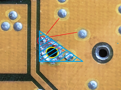
I'm attaching a image of what I mean. The yellow circle is one of the holes for soldering one of the legs of the capacitor. Do you see that the back of the motherboard is full of points, I rounded in red some of them. The photo is super zoomed, so between the mixed one and the hole of the leg of the capacitor is only 1 milimeter or even less.

You can see a red circle in the place where the mixed point was before mixing it. I added some red lines to show exactly equal points to show you what i mean with a "point".

Please can someone tell me how to solve this? Is my only working tualatin motherboard.

PD: on the other side of the motherboard, in the reverse place of these small points, are exactly the same, a small point. Don't know what is the purpose of these points. Someone know?

motherboard.png

this is the other side of the motherboard, where i used the same colors and signs to clarify which hole is which hole. As you can see, the condenser pin of the positive pole is the mixed one. Does that confirm that it is ground and it is safe to mix those circles with the negative dot of the condenser with tin?

motherboard2.png

The motherboard is this model: https://theretroweb.com/motherboards/s/dfi-ca64-tc

And the damaged condenser is this one:

dfi-ca64-tc-revb1-637397056840d804322180.jpg

Last edited by psaez on 2024-04-04, 08:09. Edited 2 times in total.

Reply 1 of 30, by Pickle

User metadata
Rank Member
Rank
Member

just one opinion and you see if anyone chimes in
basically the solder mask is gone and the solder is on the ground plane that is exposed now. I think problem your running into is ground plane is wicking the heat away. Ive had the same problem clearing ground holes. The best way to handle it is heat the board. Do you have a hot air station or hot plate?
But i think if you were able to heat the board or at least the area around it then you can keep the heat in that area longer for you to use a copper wick and flux to remove the excess solder in that area. Hopefully removing the solder bridges between the ground plane and the via. After that you would need to see if the vias are damaged and you might have to bodge wire it if the pad lifted etc.
Most times these caps can be "waddled" out where you heat one side move it out, heat our side and move it out, repeat until its clear. You might just cut the leg of the cap heat at the via and pull out with tweezers.
What part goes in the large vias (marked in yellow)? What is the capacitor used for?

Reply 2 of 30, by nhattu1986

User metadata
Rank Newbie
Rank
Newbie

That hole is connected to ground plane anyways so i think you should be fine even with solder connect to the circled part on the board. As long as the via is intact.
those small point is to connect the ground plane with the inner ground plane in the circuit board

Reply 3 of 30, by Pickle

User metadata
Rank Member
Rank
Member
nhattu1986 wrote on 2024-04-04, 00:22:

That hole is connected to ground plane anyways so i think you should be fine even with solder connect to the circled part on the board. As long as the via is intact.
those small point is to connect the ground plane with the inner ground plane in the circuit board

yeah i wasnt sure about that either, but one of the legs isnt ground and right now its hard to tell which, maybe theres trace is on the otherside of the board?

Reply 4 of 30, by nhattu1986

User metadata
Rank Newbie
Rank
Newbie
Pickle wrote on 2024-04-04, 00:29:
nhattu1986 wrote on 2024-04-04, 00:22:

That hole is connected to ground plane anyways so i think you should be fine even with solder connect to the circled part on the board. As long as the via is intact.
those small point is to connect the ground plane with the inner ground plane in the circuit board

yeah i wasnt sure about that either, but one of the legs isnt ground and right now its hard to tell which, maybe theres trace is on the otherside of the board?

The yellow circle hole should be ground, i think the cap you removed is in parallel with the cap on the right (in the picture)
you can check if the capacitor hole on the right of yellow is connected to the positive pin of the nearby capacitor

Reply 5 of 30, by majestyk

User metadata
Rank Oldbie
Rank
Oldbie

Besides that, especially when you cannot 100% avoid damaging the solder mask during the replacement process, you should never ever bend wires sidewards before soldering.
You risk unwanted shorts otherwise.

Reply 6 of 30, by ciornyi

User metadata
Rank Member
Rank
Member

It should be separated with flux and desoldering wick . But more likely you have destroyed protective varnish and just soldered bare copper layer with this dot .

DOS: 166mmx/16mb/Y719/S3virge
DOS/95: PII333/128mb/AWE64/TNT2M64
Win98: P3_900/256mb/SB live/3dfx V3
Win Me: Athlon 1700+/512mb/Audigy2/Geforce 3Ti200
Win XP: E8600/4096mb/SB X-fi/HD6850

Reply 7 of 30, by rasz_pl

User metadata
Rank l33t
Rank
l33t

That hole is fine, soldermask is peeling off the board and ground fill wicked some solder, nothing bad happened. This is a ground pin anyway.

majestyk wrote on 2024-04-04, 05:01:

you should never ever bend wires sidewards before soldering.

holy batman I didnt even notice 😮
Yeah, definitely dont do that, straighten those pins. You can bend pins _slightly_ just to make the cap not hall out of the hole when turning the board around, but ~10 not 90 degree angle, or use modeling clay/bluetack to keep components from falling out.

Open Source AT&T Globalyst/NCR/FIC 486-GAC-2 proprietary Cache Module reproduction

Reply 8 of 30, by psaez

User metadata
Rank Newbie
Rank
Newbie
Pickle wrote on 2024-04-04, 00:16:
just one opinion and you see if anyone chimes in basically the solder mask is gone and the solder is on the ground plane that is […]
Show full quote

just one opinion and you see if anyone chimes in
basically the solder mask is gone and the solder is on the ground plane that is exposed now. I think problem your running into is ground plane is wicking the heat away. Ive had the same problem clearing ground holes. The best way to handle it is heat the board. Do you have a hot air station or hot plate?
But i think if you were able to heat the board or at least the area around it then you can keep the heat in that area longer for you to use a copper wick and flux to remove the excess solder in that area. Hopefully removing the solder bridges between the ground plane and the via. After that you would need to see if the vias are damaged and you might have to bodge wire it if the pad lifted etc.
Most times these caps can be "waddled" out where you heat one side move it out, heat our side and move it out, repeat until its clear. You might just cut the leg of the cap heat at the via and pull out with tweezers.
What part goes in the large vias (marked in yellow)? What is the capacitor used for?

nhattu1986 wrote on 2024-04-04, 00:22:

That hole is connected to ground plane anyways so i think you should be fine even with solder connect to the circled part on the board. As long as the via is intact.
those small point is to connect the ground plane with the inner ground plane in the circuit board

majestyk wrote on 2024-04-04, 05:01:

Besides that, especially when you cannot 100% avoid damaging the solder mask during the replacement process, you should never ever bend wires sidewards before soldering.
You risk unwanted shorts otherwise.

ciornyi wrote on 2024-04-04, 05:10:

It should be separated with flux and desoldering wick . But more likely you have destroyed protective varnish and just soldered bare copper layer with this dot .

rasz_pl wrote on 2024-04-04, 06:58:

That hole is fine, soldermask is peeling off the board and ground fill wicked some solder, nothing bad happened. This is a ground pin anyway.

Hi, I'm adding more info as you requested: this is the other side of the motherboard, where i used the same colors and signs to clarify which hole is which hole. As you can see, the condenser pin of the positive pole is the mixed one. Does that confirm that it is ground and it is safe to mix those circles with the negative dot of the condenser with tin?

motherboard2.png

The motherboard is this model: https://theretroweb.com/motherboards/s/dfi-ca64-tc

And the damaged condenser is this one:

dfi-ca64-tc-revb1-637397056840d804322180.jpg

PD: about the bent legs, thank you, I did that because i saw it on a video, but i was going to cut them before starting the motherboard

Last edited by psaez on 2024-04-04, 08:09. Edited 1 time in total.

Reply 9 of 30, by majestyk

User metadata
Rank Oldbie
Rank
Oldbie

All the tiny vias on that plane are connected to + (-> right leg of the inductor), except for the electrolytic´s minus leg.

Cutting the bent legs will not do. You need to pull them straight upright, while the solder is liquid.

Last edited by majestyk on 2024-04-04, 08:02. Edited 1 time in total.

Reply 10 of 30, by psaez

User metadata
Rank Newbie
Rank
Newbie
majestyk wrote on 2024-04-04, 07:58:

All the tiny vias on that plane seem to be connected to + (-> one leg of the inductor), except for the electrolytic´s minus leg.

I'm sorry but my knowledge about electronics it's null. Please can you tell me if that is good or bad? I mean.. does that mean that my mixed circle and hole are safe then? that I can run the motherboard without risk of damaging it?

majestyk wrote on 2024-04-04, 07:58:

Cutting the bent legs will not do. You need to pull them straight upright, while the solder is liquid.

I noticed that the bent legs are not touching other yellow circuit parts, so I thought that simply cutting them was enough

Reply 11 of 30, by rasz_pl

User metadata
Rank l33t
Rank
l33t

So its not ground, its VCC island on both sides of the board - still fine to leave it as is.
"full of points" those are filled vias, its used to transfer heat more efficiently into the board, a heatsink.

Open Source AT&T Globalyst/NCR/FIC 486-GAC-2 proprietary Cache Module reproduction

Reply 12 of 30, by majestyk

User metadata
Rank Oldbie
Rank
Oldbie

You can put one giant solder blob over all the yellow and red vias if you like. 😀
Of yourse that´s _not_ best practice. Just insert the new polymer cap and solder i´s two legs on the backside.

No, just cutting will not be safe. This area gets quite hot during operation, so at any time, when the solder mask starts to become soft, a short can happen.

Reply 13 of 30, by psaez

User metadata
Rank Newbie
Rank
Newbie
rasz_pl wrote on 2024-04-04, 08:03:

So its not ground, its VCC island on both sides of the board - still fine to leave it as is.
"full of points" those are filled vias, its used to transfer heat more efficiently into the board, a heatsink.

majestyk wrote on 2024-04-04, 08:05:

You can put one giant solder blob over all the yellow and red vias if you like. 😀
Of yourse that´s _not_ best practice. Just insert the new polymer cap and solder i´s two legs on the backside.

No, just cutting will not be safe. This area gets quite hot during operation, so at any time, when the solder mask starts to become soft, a short can happen.

Sorry I wrote that it was the negative pole, but it's the positive pole... is still safe to have it mixed with the other circles and tin?

about the cutting of the legs... thank you, I can't understand why that guy on youtube do that then.

Reply 14 of 30, by majestyk

User metadata
Rank Oldbie
Rank
Oldbie

Yes, if by "mixed" you mean connected among each other.
Make sure your soldering iron is "strong" enough, 30 Watts or more. Then solder the yellow and the nearest 2 red vias together. It´s important the temperature is high enough so the solder flows into the yellow via and fills it.

motherboard1.png
Filename
motherboard1.png
File size
459.99 KiB
Views
472 views
File license
Public domain

Reply 15 of 30, by psaez

User metadata
Rank Newbie
Rank
Newbie
majestyk wrote on 2024-04-04, 08:18:

Yes, if by "mixed" you mean connected among each other.
Make sure your soldering iron is "strong" enough, 30 Watts or more. Then solder the yellow and the nearest 2 red vias together. It´s important the temperature is high enough so the solder flows into the yellow via and fills it.

motherboard1.png

Hi

why should I solder them? they are separated originally

Reply 16 of 30, by majestyk

User metadata
Rank Oldbie
Rank
Oldbie

Aaah, I see - I got this totally wrong in the beginning. I understood you were in doubt, because the blank area had become larger and you were unsure if you can connect them when soldering the new capacitor. Silly me...
Of cause you do not have to connect them, you can keep everything seperated as was the original stuation. Just do as everybody does, replace the capacitor and make exactly two (tiny) solderings. There´s absolutely nothing wrong with the original state.
Then again, what was the problem?
And what exactly do you mean by "mixing" the soldering points / vias?

Reply 18 of 30, by psaez

User metadata
Rank Newbie
Rank
Newbie
majestyk wrote on 2024-04-04, 12:55:
Aaah, I see - I got this totally wrong in the beginning. I understood you were in doubt, because the blank area had become large […]
Show full quote

Aaah, I see - I got this totally wrong in the beginning. I understood you were in doubt, because the blank area had become larger and you were unsure if you can connect them when soldering the new capacitor. Silly me...
Of cause you do not have to connect them, you can keep everything seperated as was the original stuation. Just do as everybody does, replace the capacitor and make exactly two (tiny) solderings. There´s absolutely nothing wrong with the original state.
Then again, what was the problem?
And what exactly do you mean by "mixing" the soldering points / vias?

Let me explain myself again.

Originally they were separated, but they are mixed now, I mean they are connected with tin. And its absolutely impossible to unconnect them. I tryed everything. So I openned this post to request for help.

So... then.. if I start the motherboard.. will it break if the red circle is still connected with the positive leg of the capacitor throught that tin on the reverse of the motherboard?

then why some of you told me that it is safe and that they are already mixed before my mistake? I can't understand.

Reply 19 of 30, by rasz_pl

User metadata
Rank l33t
Rank
l33t
psaez wrote on 2024-04-04, 14:36:

Originally they were separated

they never were, that yellow stuff underneath is copper sheet, they are all connected to it, all the little guys and that big capacitor hole, they are all one the same VCC plane.

psaez wrote on 2024-04-04, 14:36:

, but they are mixed now, I mean they are connected with tin. And its absolutely impossible to unconnect them. I tryed everything. So I openned this post to request for help.

its all ok, you didnt mess anything up. Old soldermask - the paint covering copper - started flaking off and that caused your solder to start wicking up the copper plane due to surface tension.

psaez wrote on 2024-04-04, 14:36:

So... then.. if I start the motherboard.. will it break if the red circle is still connected with the positive leg of the capacitor throught that tin on the reverse of the motherboard?

no, it was always connected to it, that capacitor is filtering voltage coming from the coil

Open Source AT&T Globalyst/NCR/FIC 486-GAC-2 proprietary Cache Module reproduction