S3thOn3 wrote on 2024-04-14, 10:31:
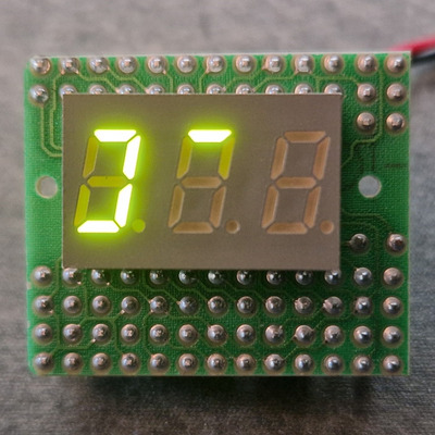
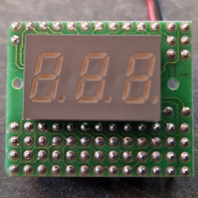
Have any of you seen this model of display before or any documentation about it?
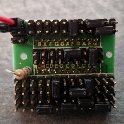
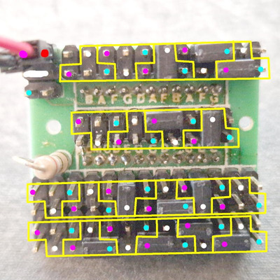
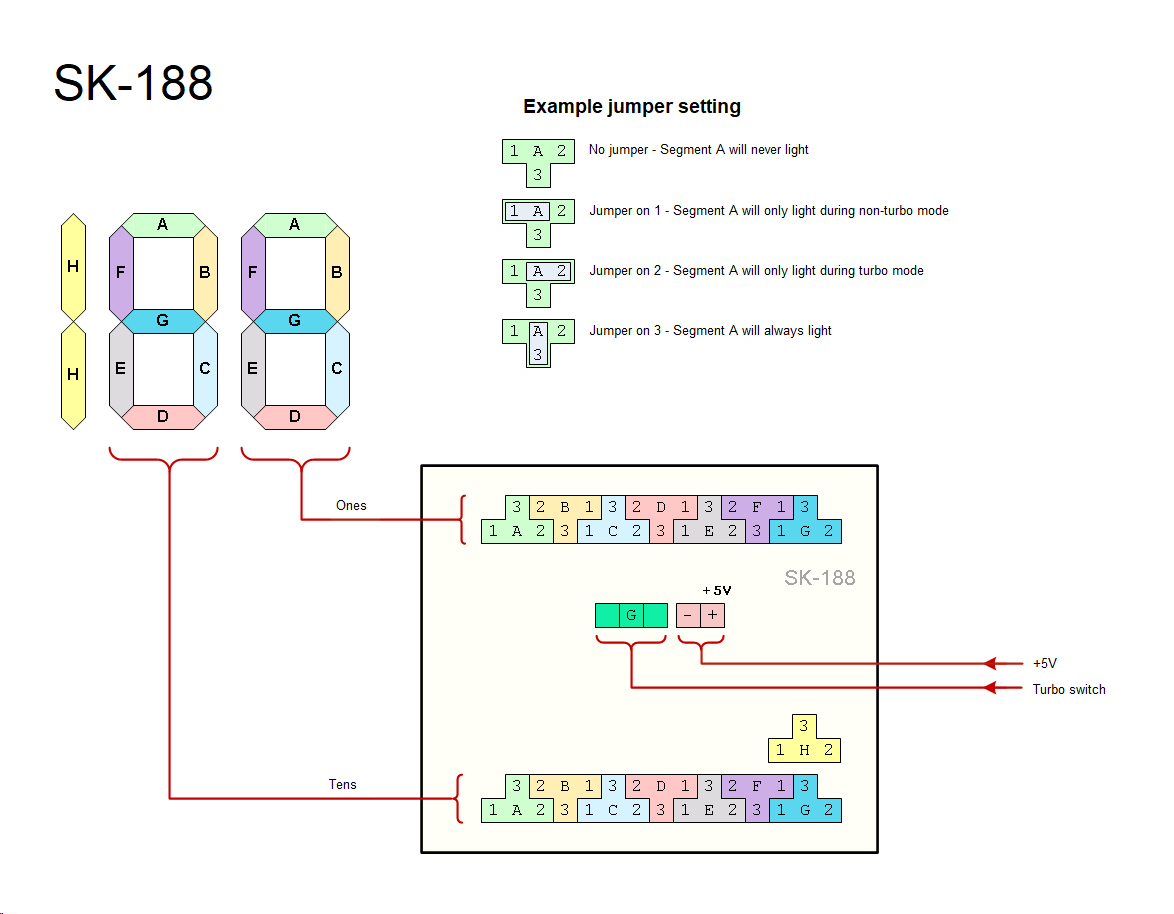
Can't help directly, but looking at what can be seen of the tracks then I think it's going to be a switch controlled version with no input from a motherboard LED header, and no output to a case LED either. So it needs 5 pins, two for power and 3 for the low-common-high header from a SPDT switch. I've had a go a sketching out how I think the jumpers are arranged, but I've no real idea which segments they light up.
This isn't the same display as you have, but it uses 5 pins for its connections: https://www.minuszerodegrees.net/led_speed_di … 0-%20SK-188.jpg
At the moment I think you have +5 on the power connector in the right place, that should be connected to one side of the resistor. The other side of the resistor should go to the COM pin on the LED module. I think you have the Gnd of the power connector connected to the magenta circuit. There are 5 segments lit and 5 jumpers connected to what I think are the magenta pins.
Working out which 'T' goes to which LED segment can be done by trial and error, although it might be possible to take a shortcut and measure for connections between the centre of each T and the LED module pins. Those pins are labelled A-G, which will probably tell you which segment it controls but not which digit.
Word of warning when testing. There's only one common resistor for the module, which means that if only a few segments are lit then not much current is drawn, so the voltage drop across the resistor will be low, so the voltage over the LED segments will be high, and possibly high enough to damage them. To ID which T controls which segment then I'd probably put jumpers between the centre and white pin of 8 of the 'T's. That should make 8 segments light up. Then remove and replace each jumper in turn to see which segment turns off. Once those 8 are identified then use a 9th jumper to test the other Ts and see which extra segment lights up.

