First post, by Nexxen

- Rank
- Oldbie
As new issues came by I decided to change the title and go with what is currently a problem.
Hello!!
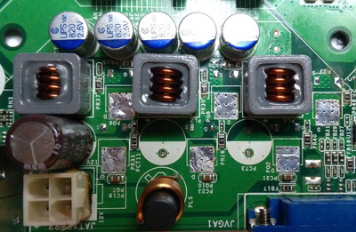
I was going to solder some new MOSFETs on this motherboard but I forgot the position of these.
Indeed I took pictures before, but it was a lot of time ago and I can't find them now.
The required area is the power MOSFETs where are 3 big electrolytic caps.
I need to read the names, one is P75N02LDG, the other P0903BDG. Which goes where? Before I kill components I thought to ask first, the area is small and soldering is a pain.
https://pdf1.alldatasheet.com/datasheet-pdf/v … /P75N02LDG.html
https://pdf1.alldatasheet.com/datasheet-pdf/v … C/P0903BDG.html
Edit: I thought that maybe it's easier to ask which of these 2 Mosfets is high and low.
Thanks in advance for any help.
Nexxen
PC#1 Pentium 233 MMX - 98SE
PC#2 PIII-1Ghz - 98SE/W2K