bristlehog wrote:
I have heard that X-Ray can be used to detect the hidden traces. Not sure though if X-Ray is harmful to electronic components.
If it was harmful, we would have broken laptops and cell phones after airport security. X-ray is also used for inspecting bad solder joints under chips.
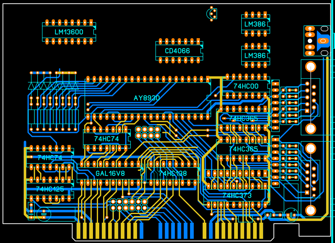
I know it is annoying and slow, but if no other equipment is available, it can be done by just looking at the PCB real hard and using multimeter. Light helps, especially with cards that have only two layers and no solid planes so light can pass it easily.
I do not suggest using multimeter in continuity test mode, as it will beep if the resistance is just under some largish threshold.
It is better to have it in resistance measurement mode and see for yourself if the measured resistance is same than just connecting the wires together.
Otherwise it will beep sometimes even if traces are not connected together, but through some component.
(OK, continuity test beep mode is fine if all components are removed, but I don't suggest that either).
Sometimes if it is hard to see, it is possible to make a good guess where traces are connected, and verify the guess with multimeter. For example, an output from a chip is connected to one or more inputs of another chips (there are exceptions if they are open collector outputs) etc.
Edit: On a side note, did anyone have a link to the programming manual? It might help figuring out the hardware as well.