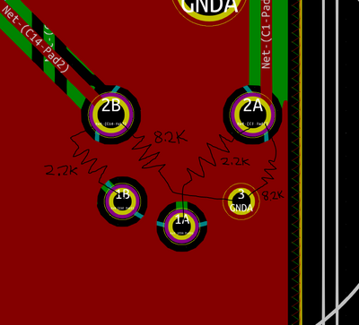
I've reached out to Eric via email one more time for information on bypassing the potentiometer, and he has kindly responded. He's really a great guy. Anyway, apparently, this is how to set it up for around 85% volume rotation:
And the resistor divider formula is Vo = Vi * Rl / (Rl + Ru) where Rl is the output line resistor (2a/b - G) and Ru is the input line resistor (1a/b to 2a/b).
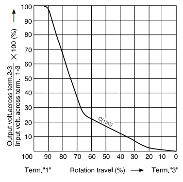
As for the potentiometer, this is the Vo/Vi vs Rotation graph:
So I settled on using 4.7KR for both Rl and Ru - this 50% divide will result in a roughly 75% rotation, pretty much what I wanted. 😀
This whould work until root42 helps me out with the Pot. Just dropping this here for future reference to anyone who needs it.
Note: I hope TubeTimeUS doesn't mind me sharing any of this but please let me know if it is a problem.
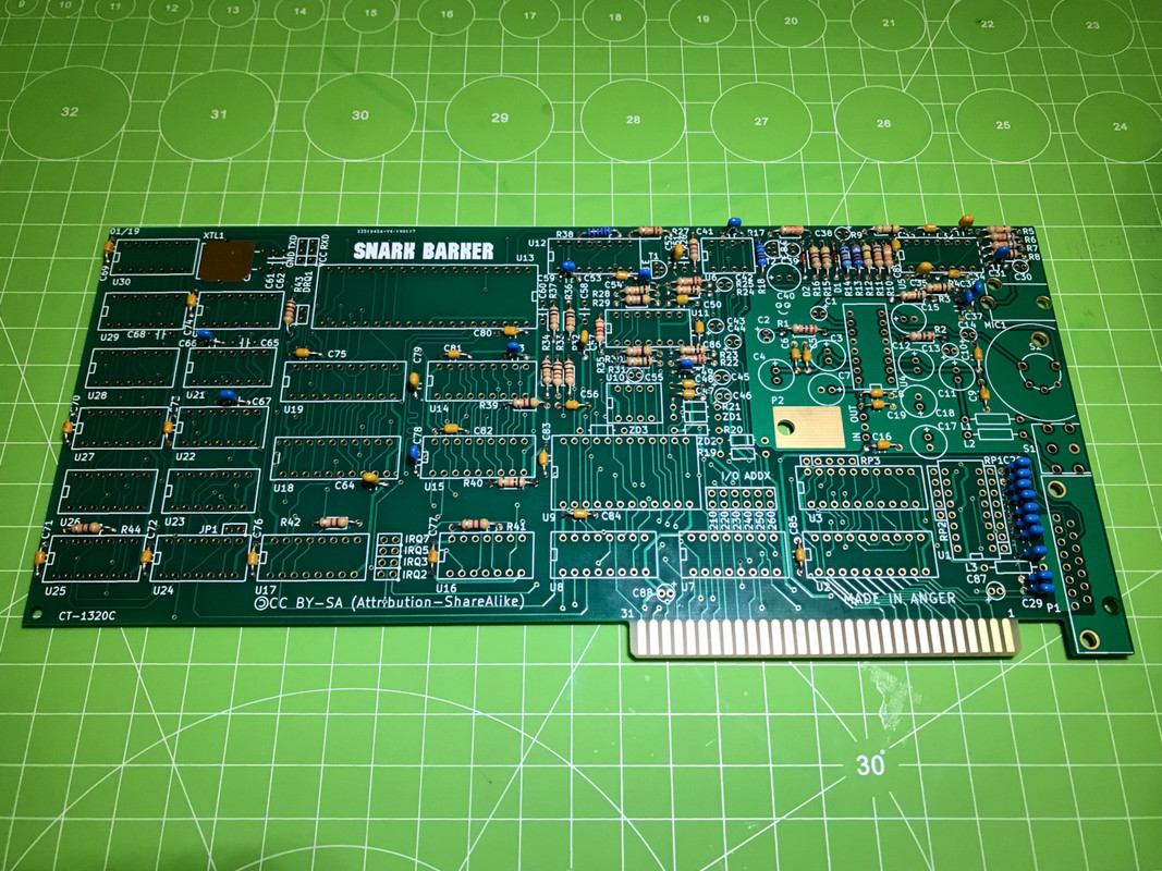
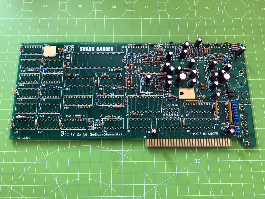
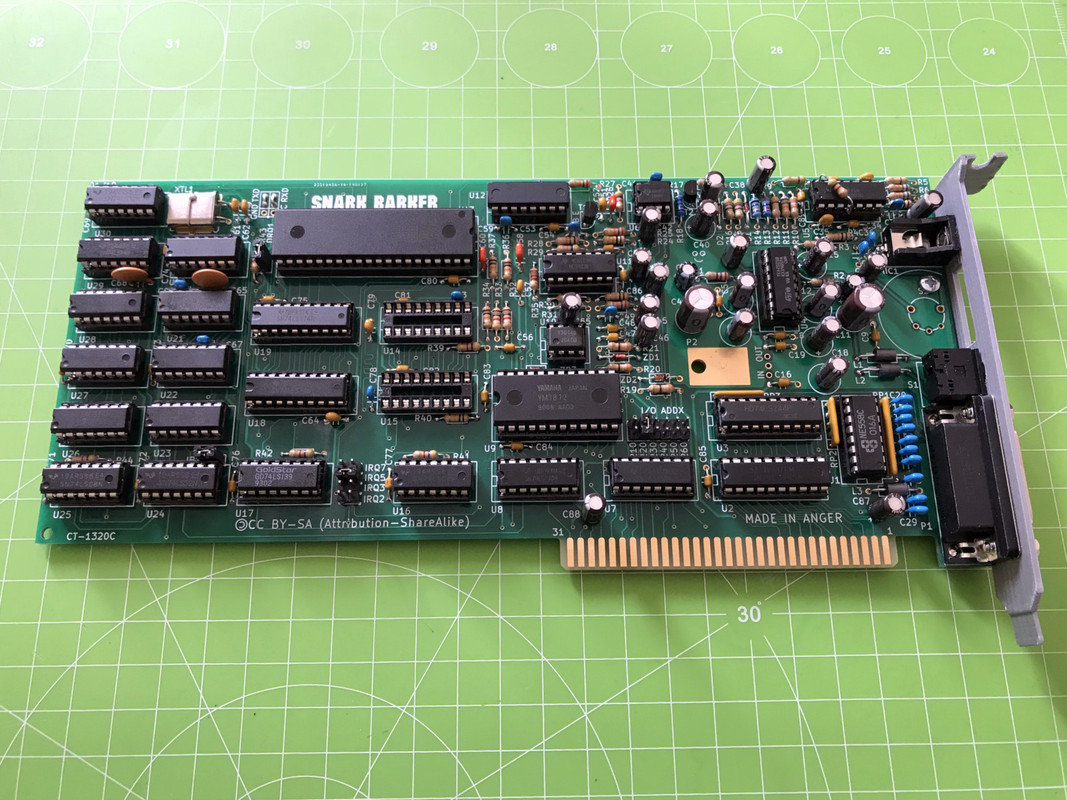
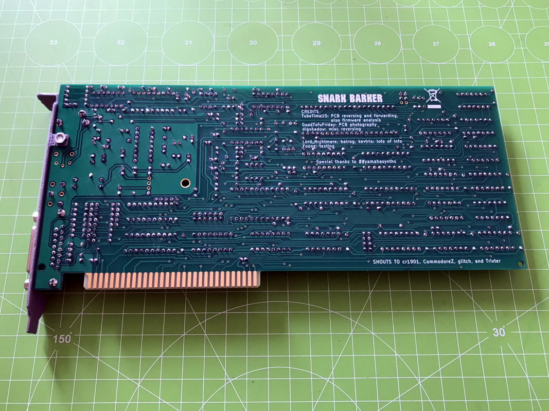
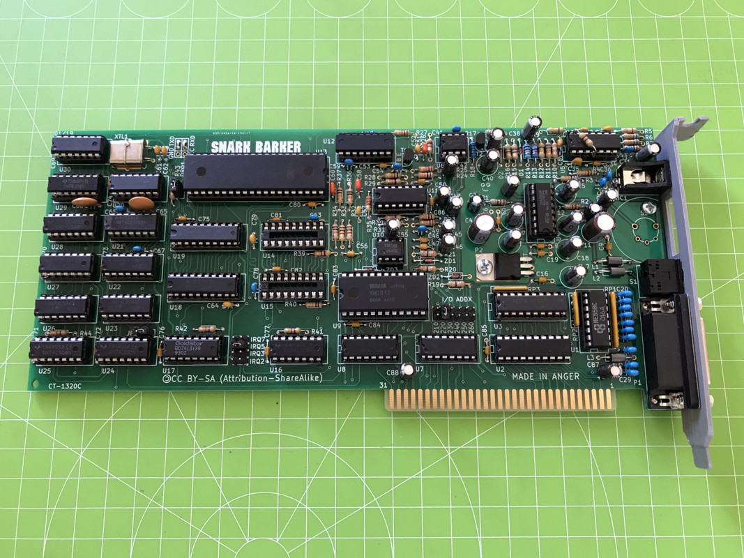
Retronautics: A digital gallery of my retro computers, hardware and projects.