I've been trying to get my CDROM drive to work on my 286 machine. I've tried to use my Edison Gold 16 (ESS) sound card [1] since it has an IDE controller on it but I can't get it to work properly.
However, I have a second ISA multi IO controller on which I can disable FDC, LTP and COM ports except for the IDE controller. However, How does the system know which IDE controller is the primary and which one is the secondary. Neither of my multi IO cards has a setting/jumper for primary/secondary.
Neither of my multi IO cards has a setting/jumper for primary/secondary.
So they both use the primary IDE address - 1F0h.
You can't use them together.
Nie tylko, jak widzicie, w tym trudność, że nie zdołacie wejść na moją górę, lecz i w tym, że ja do was cały zejść nie mogę, gdyż schodząc, gubię po drodze to, co miałem donieść.
So, I had another multi IO card that did allow me to set the range to 170-177 [1]. I disabled all other features (floppy, com, lpt, etc.) left only the HDD (IDE), but, no juice.
I also removed the second IO card. Removed my hard drive altogether and added my CDROM as the primary drive to the primary IDE. I boot from floppy with CDROM drivers (tried a bunch of different ones, including the drivers I have used on this drive in the past without any issues), still doesn't recognise the drive. I've tried 2 different drives (a Philips and a Sony one), I'm beginning to believe that there is a motherboard issue of some sort...
This is thread where I'm trying a sound card as an secondary IDE (no luck):
Why do you need two IDE connectors. The 286 can run the CDROM as slave on the primary channel just fine.
.
There's a glitch in the matrix.
A founding member of the 286 appreciation society.
Apparently 32-bit is dead and nobody likes P4s. Of course, as always, I'm open to correction...😉
Why do you need two IDE connectors. The 286 can run the CDROM as slave on the primary channel just fine.
.
I know. I brought this up in my other thread [1]. Long story short, my case is a desktop form factor and the HD sits next to the driver bays (rather than stacked above/below). This a problematic because the slave connector on the IDE cable can't reach both my HD and CDROM. I haven't found any IDE cables with a larger spacing between master and slave connector...
One option is to make up a cable yourself. The components are readily available. I found a few suitable cables when I stripped out P1-3 tower systems.
This might do the job https://www.ebay.com/itm/40-Pin-1-ft-12-Inch- … V0AAOSwwNVTr-Rv One foot extension.
There's a glitch in the matrix.
A founding member of the 286 appreciation society.
Apparently 32-bit is dead and nobody likes P4s. Of course, as always, I'm open to correction...😉
If you are using normal 40 conductor IDE cables, you can reverse the IDE cable.
Normal IDE cables have a longer cable between the host plug and the first drive plug, use that between the CDROM and hard drive, and then place the IO card close to the hard drive and plug it in at the end of the cable.
Just take off the connectors from a no-longer needed cable and press them into a cable where you want them.
It's very easy with just a little practice. And probably everybody has enough spare cables to exercise with.
I know. I brought this up in my other thread [1]. Long story short, my case is a desktop form factor and the HD sits next to the driver bays
(rather than stacked above/below). This a problematic because the slave connector on the IDE cable can't reach both my HD and CDROM.
I haven't found any IDE cables with a larger spacing between master and slave connector...
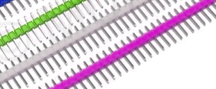
Hi, would it be possible to use a second 40pin IDE cable (1:1, only one connector on each side) and connect that to the second connector on your 40pin IDE cable ?
- I've seen some two row pin stripes in a local electronics store that could be used to connect both cables with each other.
Anyway, it's just an idea. Never tried this myself.. 🙁
"Time, it seems, doesn't flow. For some it's fast, for some it's slow.
In what to one race is no time at all, another race can rise and fall..." - The Minstrel
This is exactly why you use ISA sound cards with IDE controllers on them, they are often secondary by default or can be either primary or secondary via jumpers.
Retronautics: A digital gallery of my retro computers, hardware and projects.
This is exactly why you use ISA sound cards with IDE controllers on them, they are often secondary by default or can be either primary or secondary via jumpers.
Hi, would it be possible to use a second 40pin IDE cable (1:1, only one connector on each side) and connect that to the second connector on your 40pin IDE cable ?
- I've seen some two row pin stripes in a local electronics store that could be used to connect both cables with each other.
Anyway, it's just an idea. Never tried this myself.. 🙁
In a pinch, that should work. It would be best to have that on the end of the three-conductor cable so as not to introduce a stub off the middle connector, and thus cause reflections. Although at 8MHz IDE, you can get away with a lot of sins... 😉
IMO, every retro computer geek should have a roll of 40-conductor ribbon cable and some IDC plugs on-hand. There's just nothing like having right-sized cables.
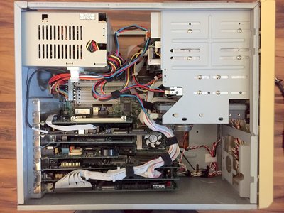
This one is especially customized. Being a mini-tower with lots of cables, it's pretty easy to turn into an unmanageable rats nest anyway. But, I also wanted to support either HDD + CD-ROM on one IDE channel, or (if I swap the controller card), 2x CD-ROMs on one channel and the HDD on another. So my IDE cable has three device connectors on it.
Then, I wanted to have my (lower) 3.5" floppy as A: and the (higher) 5.25" floppy as B:. So, I made a cable with a twist, 34-pin connector, another twist, and the card-edge connector. And then there's the SCSI ZIP drive.
The PSU harnesses have been customized as well, to provide enough connectors and at approximately the right places (plus just a little extra for servicing.)