VOGONS


Reply 180 of 424, by RetroGamer4Ever

User metadata
Rank Oldbie
Rank
Oldbie

I'm gonna order this and the X2GS with the external adapter cases, as a Birthday present for myself. I always wanted the best MIDI hardware available, but it was long gone from shelves by the time I was able to afford any of it.

Reply 181 of 424, by Salient

User metadata
Rank Member
Rank
Member
RetroGamer4Ever wrote on 2021-08-02, 13:52:

I'm gonna order this and the X2GS with the external adapter cases, as a Birthday present for myself. I always wanted the best MIDI hardware available, but it was long gone from shelves by the time I was able to afford any of it.

You won't regret this decision!

MIDI comparison website: << Wavetable.nl >>
(Always) looking for: Any Wavetable daughterboard, MIDI Module (GM/GS/XG)

Reply 182 of 424, by aitotat

User metadata
Rank Member
Rank
Member

MT-32 mode seems to have left and right channels reversed but fluidsynth mode does not. It is easy to test with Wing Commander. In the room where water drops to bucket the drop sounds are on left channel but the bucket is on right side of the screen. When switching to fluidsynth mode the water drops are on right channel (but of course intruments are wrong in GM mode but this is only for testing left and right).

Reply 183 of 424, by d0pefish

User metadata
Rank Newbie
Rank
Newbie
aitotat wrote on 2021-08-06, 08:55:

MT-32 mode seems to have left and right channels reversed but fluidsynth mode does not. It is easy to test with Wing Commander.

This is correct, there is no bug here (except maybe in Wing Commander). The 'drops' come out of the left channel on my real MT-32.

As for FluidSynth/MT-32 panning being opposite to each other, again this is correct. The MT-32 interprets MIDI CC#10 (panpot) as 0=right, 63=center, 127=left. It is believed that early versions of the MIDI standard didn't define what these controls should do, so Roland just went with this scheme for the MT-32.

Later versions of the MIDI standard (and therefore later devices released after the MT-32, e.g. SC-55) explicitly defined CC#10 to be the pan control and to interpret 0=left, 64=center, 127=right. You can verify this by comparing the MT-32 and SC-55 manuals and reading the MIDI spec.

Chances are that Origin just forgot to invert the panning messages in their MT-32 music driver.

US1wUaR.pngg
💾 Download | 📚 Documentation | Support

Reply 184 of 424, by aitotat

User metadata
Rank Member
Rank
Member

Thank you for the great information. Good to know it works just like it should. Would it be possible to add custom sysex to reverse stereo with mt32-pi.exe? Just a one more little thing to make it better than original.

Reply 185 of 424, by d0pefish

User metadata
Rank Newbie
Rank
Newbie

Yes, it should be possible to do that quite easily. Munt has a useful reverse stereo function which I can simply expose in SysEx/config option.
On my list for the next release.

US1wUaR.pngg
💾 Download | 📚 Documentation | Support

Reply 186 of 424, by dreamblaster

User metadata
Rank Oldbie
Rank
Oldbie

New revision McCake : a few size optimizations :
- moved drive bay panel connection to the side, to allow more clearance at bottom.
- moved display to position under the CM4, to reduce total thickness of the setup

Attachments

  • McCake_082021.JPG
    Filename
    McCake_082021.JPG
    File size
    1.27 MiB
    Views
    1480 views
    File license
    Fair use/fair dealing exception

Visit http://www.serdashop.com for retro sound cards, video converters, ...
DreamBlaster X2, S2, S2P, HDD Clicker, ... many projects !
New X2GS SE & X16GS sound card : https://www.serdashop.com/X2GS-SE ,
Thanks for your support !

Reply 187 of 424, by bnz99

User metadata
Rank Newbie
Rank
Newbie

I think the improvements are very good. What I started to wonder when doing my custom floppy bay is whether the pins wouldn't be better in a 2x5 IDC connector layout. They'll possibly take slightly more space, but it's much easier to actually get those cables and they are pretty cheap. Plus having shrouded pin headers on both ends would be a little more user friendly.

Reply 188 of 424, by dreamblaster

User metadata
Rank Oldbie
Rank
Oldbie
bnz99 wrote on 2021-08-08, 07:17:

I think the improvements are very good. What I started to wonder when doing my custom floppy bay is whether the pins wouldn't be better in a 2x5 IDC connector layout. They'll possibly take slightly more space, but it's much easier to actually get those cables and they are pretty cheap. Plus having shrouded pin headers on both ends would be a little more user friendly.

yes thats a good idea, except it adds height, i really want to avoid that.
see photo how my setup is, in fact the panel is ready but suitable ready to use cables are not available.
can you think of other, low height, low cost, cables that could be used ?
or is the added height for IDC connectors acceptable?

Attachments

  • DSCN0311.JPG
    Filename
    DSCN0311.JPG
    File size
    1015.22 KiB
    Views
    1462 views
    File license
    Fair use/fair dealing exception

Visit http://www.serdashop.com for retro sound cards, video converters, ...
DreamBlaster X2, S2, S2P, HDD Clicker, ... many projects !
New X2GS SE & X16GS sound card : https://www.serdashop.com/X2GS-SE ,
Thanks for your support !

Reply 189 of 424, by bnz99

User metadata
Rank Newbie
Rank
Newbie

Hm, true point. It's probably thick enough already for the next slot to be used. The problem is that many cables that are not IDC are likely again trouble to source or not long enough. The only idea I can come up with is possibly an FFC/FPC-10P connector on the WaveCake with a short flexcable that leads to an actual IDC adapter where it isn't in the way. That additional adapter surely isn't exactly nice either, but at least this stuff can be bought for cheap on AliExpress and there probably isn't any additional height due to the connector.

Reply 190 of 424, by dreamblaster

User metadata
Rank Oldbie
Rank
Oldbie

yes that would be a solution but also not ideal.

Visit http://www.serdashop.com for retro sound cards, video converters, ...
DreamBlaster X2, S2, S2P, HDD Clicker, ... many projects !
New X2GS SE & X16GS sound card : https://www.serdashop.com/X2GS-SE ,
Thanks for your support !

Reply 191 of 424, by igna78

User metadata
Rank Member
Rank
Member

Hello everyone, I was reading what has been said so far and looking at the project, and a thought occurred to me 🤔: if WP32 McCake is a waveblaster board, then it is inside the pc, why not remove the screen and buttons from the board to get more space to dedicate to the connector for front panel where is screen and buttons? (of course if the intention is to sell WP32 McCake bundled with the aforementioned front panel).
However, I think that a screen and buttons on a card inside the PC are of little use (These are just extra costs ) 😉

Reply 192 of 424, by dreamblaster

User metadata
Rank Oldbie
Rank
Oldbie
igna78 wrote on 2021-08-08, 10:36:

Hello everyone, I was reading what has been said so far and looking at the project, and a thought occurred to me 🤔: if WP32 McCake is a waveblaster board, then it is inside the pc, why not remove the screen and buttons from the board to get more space to dedicate to the connector for front panel where is screen and buttons? (of course if the intention is to sell WP32 McCake bundled with the aforementioned front panel).
However, I think that a screen and buttons on a card inside the PC are of little use (These are just little extra costs ) 😉

Hey
yes, but pcb space is not the problem, it is avoiding height

Visit http://www.serdashop.com for retro sound cards, video converters, ...
DreamBlaster X2, S2, S2P, HDD Clicker, ... many projects !
New X2GS SE & X16GS sound card : https://www.serdashop.com/X2GS-SE ,
Thanks for your support !

Reply 193 of 424, by igna78

User metadata
Rank Member
Rank
Member

Excuse me, from the last photo you posted, it seemed to me that by removing the screen, you would have recovered space (I also meant for the height of the connector) .. the photo from above deceived me 😁
Anyway as soon as this wonder is finished , there is a pc in Messina (Italy) waiting for 🤣

Reply 194 of 424, by dreamblaster

User metadata
Rank Oldbie
Rank
Oldbie

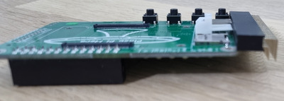
currently the floppy molex connector is the highest point

Attachments

  • mccake_height.jpg
    Filename
    mccake_height.jpg
    File size
    119.86 KiB
    Views
    1389 views
    File license
    Fair use/fair dealing exception

Visit http://www.serdashop.com for retro sound cards, video converters, ...
DreamBlaster X2, S2, S2P, HDD Clicker, ... many projects !
New X2GS SE & X16GS sound card : https://www.serdashop.com/X2GS-SE ,
Thanks for your support !

Reply 196 of 424, by igna78

User metadata
Rank Member
Rank
Member
dreamblaster wrote on 2021-08-08, 11:54:

currently the floppy molex connector is the highest point

Thanks for the photo, now I am well aware of the heights in play .. actually the screen and buttons play little on the height (or thickness) 😅
At this point, the thickness of the design could hardly be reduced further 👍

Reply 197 of 424, by 640K!enough

User metadata
Rank Oldbie
Rank
Oldbie
dreamblaster wrote on 2021-08-08, 07:34:

can you think of other, low height, low cost, cables that could be used ?
or is the added height for IDC connectors acceptable?

Why not a right-angle IDC connector? In surface-mount form, they shouldn't add more than a few millimetres to the overall thickness of the whole assembly. Using the unshrouded variety would reduce that slightly, as well. If it's really a concern, then try varying the number of rows used, or the pin/row pitch.

Reply 198 of 424, by bnz99

User metadata
Rank Newbie
Rank
Newbie

It's actually true. I have tested a two-row right angled socket against the floppy connector and the floppy connector is still higher. So an unshrouded 2-row right angled pin header might not be as high as we thought.

Attachments

  • 20210809_075513.jpg
    Filename
    20210809_075513.jpg
    File size
    409.11 KiB
    Views
    1325 views
    File license
    Public domain

Reply 199 of 424, by RetroGamer4Ever

User metadata
Rank Oldbie
Rank
Oldbie

Go ahead and take your time. This is obviously more complex than a DREAM-based synth card, so you might as well try some things out before you commit to mass-manufacturing. I myself have no use for the buttons and display, but I understand the reasoning behind them.