VOGONS


First post, by ElBrunzy

User metadata
Rank Oldbie
Rank
Oldbie

I have a computer build with an mt32, guspnp and sb1.5. I hooked the mt32 into the line-in of the guspnp. The sb1.5 output directly to my receiver since I bought it for an SAA1099 project. But as times goes, I end up wanting to play games using the mt32 for music and soundblaster for audio. And I would like to avoid using sb emulation from the gus.

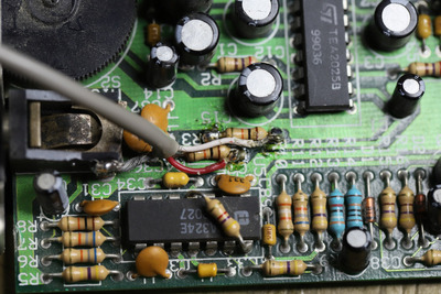
So I want to plug the SB into the CD-in of the GUSPnP but the SB card only have an amplifier-out with a big volume knob that I often crank all the way up or down when I mess around the computers wire. So I'm not very found of hooking directly the amp-out of the sb1.5 into the guspnp in fear to fry something. Maybe I can find a SMD volume knob and swap it, then find a safe value to send to the cd-in of the guspnp ? But I think I could also try to intercept the card signal before it goes to the amplifier. Since I'm afraid to break anything any help or comments would be appreciated before I start to look at it. I've read a thread from anonymous-coward that want to do the same thing for a sbpro so I assume it's possible for a sb1.x too.

Reply 1 of 4, by Thermalwrong

User metadata
Rank Oldbie
Rank
Oldbie

From what I can see on the snark barker's schematic that TubeTime put together, you could do that potentially by wiring the left channel to either positive or negative of Capacitor C1, then the right channel should be either leg of C14. Those both come straight out of the volume wheel and feed into the amplifier.

Reply 2 of 4, by ElBrunzy

User metadata
Rank Oldbie
Rank
Oldbie

oh wow ! Awesome schematic is that! Thanks to point it out to me. I think I will try it today. But dont you think it would be better to interface the line-out after R4 and R3, just before the volume wheel ? So that would give a more consistent line-out ?

Reply 3 of 4, by ElBrunzy

User metadata
Rank Oldbie
Rank
Oldbie

Thank to your help Thermalwrong, I could quickly close this case. I now have a consistent and secure line level I can feed to the GUSPnP via it's internal cd-in connector. It bypass and do not disable the amplified output. I was a bit careless at first and solder the wrong side of the R3 and R4 resistances that's why it look a bit messy, but it work great and I will now put a big drip of hot glue over it. I used the convenient microphone skeleton jack elbow to attach the ground. Still I ever wonder if it's important to tie ground in between internal soundcards connectors of a same computer, oh well...

20210215144553_IMG_0699.JPG
Filename
20210215144553_IMG_0699.JPG
File size
631.48 KiB
Views
208 views
File license
Public domain

Reply 4 of 4, by Jo22

User metadata
Rank l33t++
Rank
l33t++

Look's fine!

By the way, you can also use caps for galvanic insulation.

I generally often use 4,7uF to 10uF for that (for my radio hobby).
They do block DC, so that only the AF (AC) can go through.
Hm. The value of the caps epends on the frequency range, also.
If it's too big, it will work too much like a low-pass filter.
Anyway, the values above might be good for approx a 4KHz range (8000Hz sampling rate).

Another idea would be a small AF transformer, say 1:1, from Radio Shack etc.

The PC speaker might be an exception, though. It's essentially using DC only, since it's a TTL devices (5v/0v) that's toggled on/off very rapidly..

An opto-coupler would be the only alternative to that.

Anyway, these are just ideas that come to mind.
Since everything uses the same ground, it's use case is questionable. As you pointed out yourself.
Hm. Maybe a shielded coaxial cable can avoid noise flowing in, too.

"Time, it seems, doesn't flow. For some it's fast, for some it's slow.
In what to one race is no time at all, another race can rise and fall..." - The Minstrel

//My video channel//