VOGONS


Reply 380 of 861, by appiah4

User metadata
Rank l33t++
Rank
l33t++

This is what I get from the TTL, so I'm guessing there is hope? 😁

Attachments

Retronautics: A digital gallery of my retro computers, hardware and projects.

Reply 381 of 861, by MJay99

User metadata
Rank Member
Rank
Member

That certainly looks perfectly fine for the pico's GUS fw after startup. So, the issue really seems to be between the ISA and the Pico's pads...

Does polpo's debug test maybe reveal anything?
-> Re: PicoGUS: ISA sound card emulator with Raspberry Pi Pico (Gravis Ultrasound, AdLib, MPU-401, Tandy, CMS)

I think I was able to piece together the image's artifacts enough to recognize something suggesting the correct ICs in a few spots (just barely for U5 and U6).
For U7 and U9 that wasn't possible though - are they verified to be the right IC in the right place?

Reply 382 of 861, by polpo

User metadata
Rank Member
Rank
Member

Visually, everything looks OK to me. As MJay99 points out, it's not possible to read U7 or U9 but all other components look correct. The soldering looks excellent!

I've been thinking about creating a debug firmware and a program in DOS that writes to certain IO addresses to try and point to potential problems in the different chips. For example, if the upper 2 bits of the address are incorrect, it'd U2's fault, the middle 4, U4, or the bottom 4, U3. If no address activity read at all, U5 or U6, etc...

Reply 383 of 861, by appiah4

User metadata
Rank l33t++
Rank
l33t++

Thanks for the tips. I've done the DEBUG trick and this is the result:

-o 343 aa
-i 343
FF
-

I'm guessing this means:

This writes aa to the GUS register select register and then reads it back, so it should print back aa. If you get ff back then something is preventing the PicoGUS from responding to bus events: IOR/IOW is not working, or the address or data lines or shorted. If you get something other than aa or ff, there’s probably an issue with one or more of the data lines being shorted.

Which ICs should I concentrate on?

Retronautics: A digital gallery of my retro computers, hardware and projects.

Reply 384 of 861, by Shreddoc

User metadata
Rank Oldbie
Rank
Oldbie
appiah4 wrote on 2023-07-19, 05:49:
Thanks for the tips. I've done the DEBUG trick and this is the result: […]
Show full quote

Thanks for the tips. I've done the DEBUG trick and this is the result:

-o 343 aa
-i 343
FF
-

I'm guessing this means:

This writes aa to the GUS register select register and then reads it back, so it should print back aa. If you get ff back then something is preventing the PicoGUS from responding to bus events: IOR/IOW is not working, or the address or data lines or shorted. If you get something other than aa or ff, there’s probably an issue with one or more of the data lines being shorted.

Which ICs should I concentrate on?

I would concentrate on U2, U3, U4. All my builds had issues with (some of) those, initially. The 2-3 pins at the end of each drag, that is a particularly susceptible area, because it is where some excess solder typically sloughs off the iron when the iron is lifted away at the end of a drag.

You could also do a close visual check of the left side of U5 (under R1), to ensure that the solder properly adhered to those 7 pins and pads. I only mention it because that chip position is slightly shunted to one side.

The soldering looks very good overall. If you want to post further photos, I'm sure we are all happy to inspect those too, for example, side-on views of the ICs, to see the small soldering detail as much as possible. + the card rear.

Reply 385 of 861, by appiah4

User metadata
Rank l33t++
Rank
l33t++

Thanks, I will take another look at everything yo said and do continuity checks with the multimeter.. In the meantime, here are better photos of my first attempt at SMD soldering 😅

Attachments

Retronautics: A digital gallery of my retro computers, hardware and projects.

Reply 386 of 861, by rafpereira

User metadata
Rank Newbie
Rank
Newbie

I noticed that PicoGUS has a narrow ISA Bus working frequency range while testing it in a UMC 386DX board.

At 33Mhz FSB, the ISA Clk was set:
1/2 - pguinit doesn't recognise it (16mhz)
1/3 - pguinit doesn't recognise it (11mhz)
1/4 - pguinit initialised it (8mhz) and works fine
1/5 - pguinit initialised it (6.7mhz) and works fine

The ISA clock in that board will restrict on how fast the graphics and IDE card can operate., and some of the latest cards will do fine up to 1/2 (16mhz)
Is there a way to increase the ISA clock frequency acceptable to PicoGUS card?

Reply 387 of 861, by root42

User metadata
Rank l33t
Rank
l33t
appiah4 wrote on 2023-07-19, 09:12:

Thanks, I will take another look at everything yo said and do continuity checks with the multimeter.. In the meantime, here are better photos of my first attempt at SMD soldering 😅

Looks fine, but the pico pinheader looks a bit sloppy on this area:

IMG_7114.jpeg
Filename
IMG_7114.jpeg
File size
93.03 KiB
Views
1410 views
File license
CC-BY-4.0

YouTube and Bonus
80486DX@33 MHz, 16 MiB RAM, Tseng ET4000 1 MiB, SnarkBarker & GUSar Lite, PC MIDI Card+X2+SC55+MT32, OSSC

Reply 388 of 861, by appiah4

User metadata
Rank l33t++
Rank
l33t++

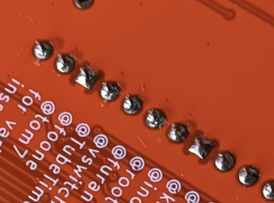
Thanks @root42 I'll go over those. (EDIT: Some of the pins were soldered a bit thin so I went over each, made no difference I'm afraid)

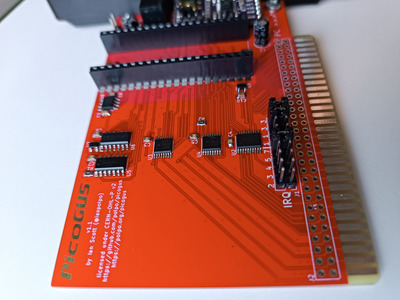
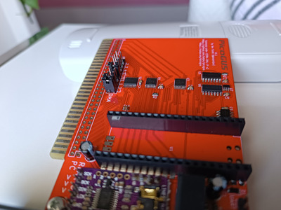
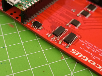
I reflowed U2-U3-U4-U5-U6-U7-U8 for the fourth time to no effect.

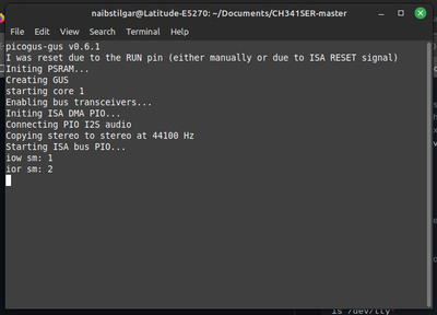
I tried the adlib firmware to see if I get anything out of that, but no - OPL2/3 not detected on the ISA Bus.

I'm thinking there is no communication between the ISA bus and PicoGUS somehow? What could be the fault? I don't want to start blindly replacing ICs tbh. Maybe @polpo will have a more informative debug firmware 😅

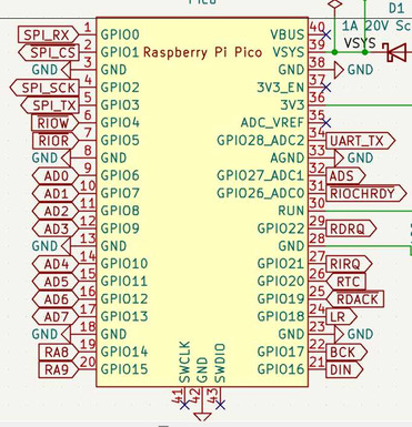
I tried going through the schematic PDF to figureout which ISA bus pins connect to what but it's not that easy to figure out all of them and check them one by one.

Regardless, I started doing just that. So far, the following pins are confirmed connected to the relevant ICs: D7-D0, I/OCHRDY, AEN, A0-A9

Retronautics: A digital gallery of my retro computers, hardware and projects.

Reply 389 of 861, by MJay99

User metadata
Rank Member
Rank
Member

So the low hanging fruits are slowly all collected... 😁

Do you happen to have an oscilloscope or logic probe? If so, you could check the RIOW/ RIOR and AD / RA lines (all on the left side) and maybe also pins 25 to 32 on the right side of the pico for some life in them and maybe isolate an IC by that (the RUN pin will be high and doesn't need checking since the pico itself is alive):

pico.jpg
Filename
pico.jpg
File size
64.96 KiB
Views
1364 views
File license
CC-BY-4.0

Just to be sure: U7 and U9 are verified to not have been accidentally swapped?

Last edited by MJay99 on 2023-07-19, 13:37. Edited 1 time in total.

Reply 390 of 861, by AEV80

User metadata
Rank Newbie
Rank
Newbie

I know it's a long shot but have you checked for shorts on the socket and header pins on both the PicoGUS and Pi Nano?

When I built a Snark Blaster this happened to me under one of the IC sockets (too much solder and bridged on top side) and it wasn't visible until the socket was removed.

Also check for any cut tracks, an accidental scratch with a soldering iron can be enough to cut fine tracks (also happened when I built the Snark Blaster but I noticed it when it happened).

Reply 391 of 861, by appiah4

User metadata
Rank l33t++
Rank
l33t++
MJay99 wrote on 2023-07-19, 13:34:
So the low hanging fruits are slowly all collected... :D […]
Show full quote

So the low hanging fruits are slowly all collected... 😁

Do you happen to have an oscilloscope or logic probe? If so, you could check the RIOW/ RIOR and AD / RA lines (all on the left side) and maybe also pins 25 to 32 on the right side of the pico for some life in them and maybe isolate an IC by that (the RUN pin will be high and doesn't need checking since the pico itself is alive):
pico.jpg

Just to be sure: U7 and U9 are verified to not have been accidentally swapped?

More ISA pins checked and correctly connected: IRQ2,3,4,5,7, DACK1,DRQ1, DACK3,DRQ3, IOR, IOW

I just received an oscilloscope in the mail, but have zero experience using it. Guide me through what you need me to do and I'll do it tomorrow 😅

U7 and U9 are both marked. C065.. Uh?

EDIT: I just checked, it looks liked I used two 74LVC1G06 for U7 and U9.. I need to order 74LVC1G00 and replace U7!

Retronautics: A digital gallery of my retro computers, hardware and projects.

Reply 392 of 861, by MJay99

User metadata
Rank Member
Rank
Member
appiah4 wrote on 2023-07-19, 13:57:

U7 and U9 are both marked. C065.. Uh?

Maybe we're onto something here... these two should be different.
Mine are marked C00J (74LVC1G00) and C06J (74LVC1G06)

So at least U7 seems to be a wrong IC,
C065 could be correct for U9: http://www.smdmark.com/en-US/smd-code-c065.html

Reply 393 of 861, by MJay99

User metadata
Rank Member
Rank
Member
appiah4 wrote on 2023-07-19, 13:57:

EDIT: I just checked, it looks liked I used two 74LVC1G06 for U7 and U9.. I need to order 74LVC1G00 and replace U7!

Perfect. Guess we finally found our culprit 😉

Reply 394 of 861, by appiah4

User metadata
Rank l33t++
Rank
l33t++
MJay99 wrote on 2023-07-19, 14:21:
appiah4 wrote on 2023-07-19, 13:57:

EDIT: I just checked, it looks liked I used two 74LVC1G06 for U7 and U9.. I need to order 74LVC1G00 and replace U7!

Perfect. Guess we finally found our culprit 😉

U7 has been removed.

Attachments

Retronautics: A digital gallery of my retro computers, hardware and projects.

Reply 395 of 861, by shimart

User metadata
Rank Newbie
Rank
Newbie

I'm interested in creating Picogus. I noticed that the PCB Gerber version has been updated to 1.1.1, but I've already placed an order for the 1.1 version. I'm curious about the changes from version 1.1 to 1.1.1

Reply 396 of 861, by MJay99

User metadata
Rank Member
Rank
Member

The PCB you ordered should be completely fine, just make a mental note that the 1nF cap goes to the PSRAM, not anywhere else and order a SN74CB3T3245 instead of a 74LVC244, if you happen to see that in any bom version 😉

Here's polpo's comment about it from Re: PicoGUS: ISA sound card emulator with Raspberry Pi Pico (Gravis Ultrasound, AdLib, MPU-401, Tandy, CMS):

polpo wrote on 2023-07-12, 14:48:

There's no functional change with the v1.1.1 gerbers, but it solves a long-standing issue with the KiCad project, the gerbers in the repo, the bom.csv file, and interactive bom at https://polpo.org/picogus/bom being out of sync with each other. Specifically it's about the 1uF decoupling capacitor on the PSRAM chip (U8) being mixed up with the 0.1uF decoupling capacitor on U9. In the v1.1 hardware revision, this 1uF capacitor was marked C9 on the board, but the BOM and KiCad had that capacitor as C10. This means when people were building their boards, they were putting the 1uF capacitor on U9 instead. Ultimately it doesn't really seem to affect performance, but it was bugging me so I fixed it. I also updated the KiCad project to specify a SN74CB3T3245 for U2, the recommended part number, instead of the 74LVC244 that I started off with.

Reply 397 of 861, by appiah4

User metadata
Rank l33t++
Rank
l33t++

Uh.. I'm confused now. In this photo from the Picogus github wiki, C10 is located at the top, C9 is located at the bottom:

215666529-fc694b8f-aec3-4679-87df-b53d0c406c99.jpg

Is the above photo the 1.1.1 board? On my card, it is the other way around SMH..

PicoGUS v1_1.jpg
Filename
PicoGUS v1_1.jpg
File size
387.87 KiB
Views
1230 views
File license
CC-BY-4.0

If that is the case, and if the BOM lists C9 and C10 correctly (but they are incorrectly silkscreened) then I may have them reversed as well? 🙄

Last edited by appiah4 on 2023-07-20, 07:58. Edited 1 time in total.

Retronautics: A digital gallery of my retro computers, hardware and projects.

Reply 398 of 861, by MJay99

User metadata
Rank Member
Rank
Member

The github image indeed says v1.1 but looking at my card (with a v1.1 marking also), the refs for C9 and C10 are swapped compared to this one, so it might show an already silently updated 1.1.1 variant... 😉

But whatever the refs or bom says: the cap on the top, marked as C10 on the github image, should be 1nF and the one on U9 should be a 100nF.

Even if you did solder them the other way, it doesn't really seem to affect the stability of the card (the 1nF is recommended by the PSRAM's datasheet, for decoupling afair) - I still have one of those cards with them being soldered in the wrong place, also and it has been working perfectly fine.

Still doesn't hurt to correct them when you're at it, of course 😀

Last edited by MJay99 on 2023-07-20, 08:12. Edited 1 time in total.

Reply 399 of 861, by appiah4

User metadata
Rank l33t++
Rank
l33t++

The photo I posted ABOVE is not mine, it's from the PicoGUS git page.. the one on the bottom is mine, and on mine the top cap is marked C9 (and likely populated 100nF in error) and the bottom cap is marked C10 (and likely populated 1uF in error) 🙁

To clarify, this his HOW IT SHOULD BE:

- Top should be C10, and populated with 1uF
- Bottom should be C9, and populated with 100nF (0.1uF)

Right?

Retronautics: A digital gallery of my retro computers, hardware and projects.