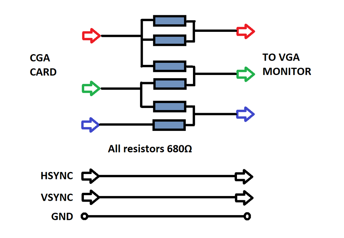
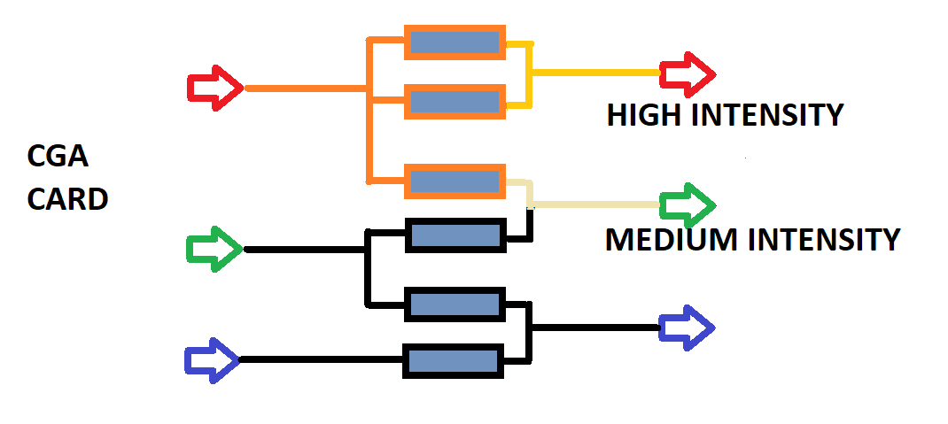
The arrangement looks only strange if you look at it the way you do. Assume (even that isn't perfectly true) that the CGA card as the sender keeps the voltage at the RED, GREEN and BLUE constant at 0V and "5V" (will be more like 4V on TTL logic). The signal from the BLUE output will go to the BLUE input, and you are right that there will be some effect from the BLUE output visible at the GREEN output. The effect will not spread past the GREEN output, though, because the CGA card will actively keep the GREEN output at a constant level, whether it gets "low" or "high" feedback from the BLUE output.
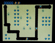
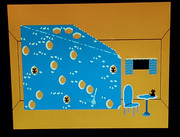
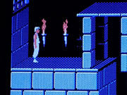
An easier way to look at the circuit is thus to just look at the VGA monitor inputs, and see how they are driven: The "blue" input is driven to the average of the GREEN and BLUE outputs. The GREEN input is driven to the average of the GREEN and RED outputs, and the RED input is driven to by the RED output only. The will create false colors, but this is intended by the OP, because the genuine CGA colors don't look that great, and a lot of people are tired of the genuine CGA colors, so this adapter gives CGA graphics a yet unknown (and thus fresh) look.
This circuit is not connecting the "intensity" output of the CGA card, which causes the distinction between "bright" and "normal" colors to disappear. This is not that much an issue in CGA graphics modes, as the 4-color graphics modes support only one kind of "normal" or "bright" colors (except for the "background" color), so you won't see mixtures between the normal and bright in graphics modes. In text modes the loss of 8 colors might be more notable - but in text mode you might not like the false colors anyway. You could modify this adapter to take care of the intensity bit by using 1K resistors instead and adding a 1K resistor from the "INTENSITY" output to each of of the "RED", "GREEN" and "BLUE" VGA monitor intput.
