VOGONS


First post, by konc

User metadata
Rank l33t
Rank
l33t

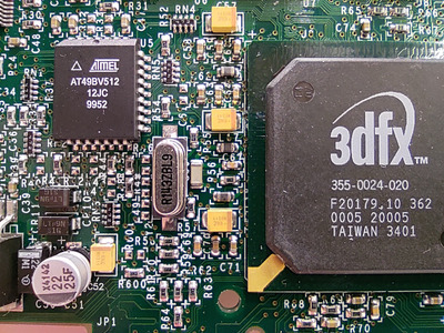
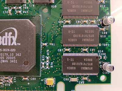
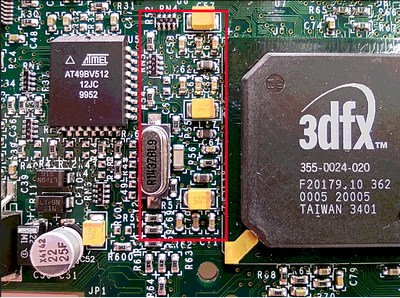
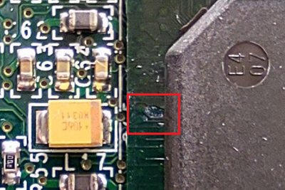
Hi guys, another Voodoo3 repair attempt thread. I got this card in a sad state as non-working. It was missing the bracket, the heatsink, the 3 capacitors on the right and the one next to the feature connector.

V3.jpg
Filename
V3.jpg
File size
1.42 MiB
Views
553 views
File license
Fair use/fair dealing exception

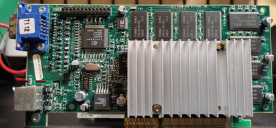
But it's working, Glide included, and no stability issues so I thought it's worth the effort.
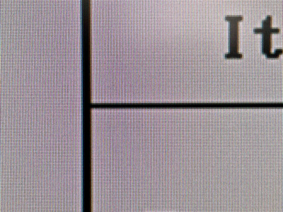
The issue I'm having is bad output with "trembling" characters. It's related to the resolution/refresh, for example the BIOS/POST screen looks only a bit blurry, while in the DOS mode the problem is worse and apparent.

This video demonstrates the problem, it might be too compressed by the hosting site but it still accurately shows what the characters look like. If anyone wants to see another recording or photo please let me know.
https://imgur.com/dwKSB0o

I did solder the 4 missing capacitors and while I was at it I changed the other 4 electrolytic as well. Also the computer/monitor/power/cables etc are irrelevant. The card has the same behavior in a completely different environment and, the opposite, another identical card works fine in the test system.

So, any ideas what might be causing this? Any suggestions for actions?

Reply 2 of 11, by Tiido

User metadata
Rank l33t
Rank
l33t

This looks like pixel clock generation issue, likely in the analog domain. You'll probably have to carefully inspect some passives around the main chip, maybe even replace a tantalum.

T-04YBSC, a new YMF71x based sound card & Official VOGONS thread about it
Newly made 4MB 60ns 30pin SIMMs ~
mida sa loed ? nagunii aru ei saa 😜

Reply 4 of 11, by konc

User metadata
Rank l33t
Rank
l33t
nuno14272 wrote on 2024-05-16, 12:49:

I woult try a bios re-flash.

I took the opportunity to upgrade to the latest version, but as expected it didn't make any difference.

Tiido wrote on 2024-05-16, 12:01:

This looks like pixel clock generation issue, likely in the analog domain. You'll probably have to carefully inspect some passives around the main chip, maybe even replace a tantalum.

Bummer, I did desolder and check the 5 yellow tantalum capacitors around the main chip and they all measure fine (10-11.5 μF). Also I soldered them back in different positions, just to be extra safe, but nothing changed. Then I checked for shorts (continuity/near zero resistance between the poles) all the small capacitors and resistors in circuit, but none beeped. My inexperienced eyes see nothing suspicious around the chip, if anyone spots something please say so!

IMG_20240516_212049_2.jpg
Filename
IMG_20240516_212049_2.jpg
File size
637.63 KiB
Views
351 views
File license
Public domain
IMG_20240516_212057_2.jpg
Filename
IMG_20240516_212057_2.jpg
File size
510.74 KiB
Views
351 views
File license
Public domain

Reply 5 of 11, by nuno14272

User metadata
Rank Member
Rank
Member

the problem are the eletrolitic capacitors.. Those are the ones to change... That's my second guest..

1| 386DX40
2| P200mmx, Voodoo 1
3| PIII-450, Voodoo 3 3000

Reply 6 of 11, by konc

User metadata
Rank l33t
Rank
l33t
nuno14272 wrote on 2024-05-20, 14:05:

the problem are the eletrolitic capacitors.. Those are the ones to change... That's my second guest..

All 8 are new,

konc wrote on 2024-05-08, 10:49:

I did solder the 4 missing capacitors and while I was at it I changed the other 4 electrolytic as well.

Reply 7 of 11, by smola

User metadata
Rank Newbie
Rank
Newbie

Check this, very similar issue:
http://3dfx.pl/public_html/yabbfiles/Attachme … terferencja.mp4

Repair & fix (pl lng, use translator):
http://3dfx.pl/cgi-bin/yabb2/YaBB.pl?num=1617221455/111#111

Final result in attachment.

Attachments

my repairs: mobo index :: vga index :: requests

Reply 8 of 11, by konc

User metadata
Rank l33t
Rank
l33t
smola wrote on 2024-05-20, 18:06:

Check this, very similar issue:

This does indeed look very similar! The only problem in this case is that after replacing all 8 big electrolytic and measuring the 5 big yellow tantalum capacitors, there are only the tiny ones left. And I wouldn't know where to start replacing since there is no obvious short. Are the small ones really capable of causing this behavior? If so I guess I could start slowly replacing them, provided that I also find a component map to get their values.

Reply 9 of 11, by Tiido

User metadata
Rank l33t
Rank
l33t

You can do the finger test, find a place where the finger starts to make the problem worse (avoid the crystal and its capacitors, that will absolutely affect stuff and give a false lead).

T-04YBSC, a new YMF71x based sound card & Official VOGONS thread about it
Newly made 4MB 60ns 30pin SIMMs ~
mida sa loed ? nagunii aru ei saa 😜

Reply 10 of 11, by smola

User metadata
Rank Newbie
Rank
Newbie

Well, that 8 ele caps could be weak quality/bad type. They look like common ones. I'd go for better quality caps, especially for voodoo cards. Usually I use hq poly/tantalum caps, very rare low esr ele type, never common type. You can measure noise level on power lines, but it requires oscilloscope. "Safe" ripple level is, I'd say, under 30mV (good if less than 3% of nominal voltage, best if under 1%) . Low quality/common caps can increase it, it was confirmed few times in the past during other repairs. Also, resoldering same tantalum caps is not good idea, they really don't like high temperatures, and can lose their orig params. They need to be soldered very quick, approx. in 2 seconds max, heating over 3s can damage them - there is pdf with explanation "how to solder" tantalum caps made by vishay (try to find: "Guidelines for Replacing Tantalum Capacitors Using a Soldering Iron"). Good luck!

my repairs: mobo index :: vga index :: requests

Reply 11 of 11, by sdz

User metadata
Rank Member
Rank
Member

I suspect Tiido is right, it looks like an analog domain issue. The analog domain on the Avenger is powered from the core voltage, usually 2.7V. The only electrolytic cap on your card that is on that rail would be C51, and perhaps C50 (can't tell if it's tantalum or electrolytic cap).

There are three rails powering the analog domain:
-first rail powers AGP_PLL_VDD (Avenger ball D18)
-second rail powers PLL_AVVD0 and PLL_AVVD1 (Avenger ball B18 and C19)
-third rail powers the DAC_AVDD (Avenger ball C11 and D11)

Each rail is tapped from the 2.7V rail, has a series ferrite bead (600 ohms impedance at 100MHz), followed by : 1x tantalum capacitor, 1x 100nF ceramic cap, 1x 10nF ceramic cap, 1x 1nF ceramic cap. All these parts are located here:

S1.png
Filename
S1.png
File size
453.45 KiB
Views
136 views
File license
Public domain

I doubt the ceramic capacitors are damaged, but it's not impossible (cracked ceramic capacitors can fail open, and behave like they're not there, without shorting the rail).
You could check the voltage on both sides of the ferrite beads, and the output voltage of the regulator. You should only see around 2.7V.
As smola indicated, if you have an oscilloscope, measure the ripple on this rail.

Also check for damage on the Avenger IC, it looks a bit weird right there the PLL/DAC supplies are located:

S2.png
Filename
S2.png
File size
452.67 KiB
Views
136 views
File license
Public domain

You could also try to replace the 14.318MHz crystal.