VOGONS


First post, by alextpp7

User metadata
Rank Newbie
Rank
Newbie

Hi,
I found a huge Grundig 33" CRT TV in the street. After a complete cleaning and a fix of the anode which gave some arcs, I made it work.

The main problem is that if I push the contrast above 15 or 20%, the focus goes away. It is still very enjoyable but I wish I can get a little bit more focus with better contrast.

I adjusted the focus knob on the flyback but it doesn't help much. I lowered the luminosity to the point where blacks won't become grey.
Service menu doesn't have settings to deal with colors, except white balance, but it doesn't help.

My question is to know if by adjusting the G2 (it is not set at max value for now), could it help getting more contrast without losing focus ?

I know the CRT is probably worn out, but I wish I can get a bit more contrast without losing focus -_-

Thanks !

PS : I can't adjust colors from RGB scart mode. But I guess that if I could lower them a little bit, I could get some more focus ... Do you agree with this ?

PS 2 : I've got another Grundig, this one gives perfect focus even with a contrast set at 100% .. sadly it is a 22" CRT TV only ..

Last edited by alextpp7 on 2021-07-02, 12:47. Edited 1 time in total.

Reply 1 of 19, by alextpp7

User metadata
Rank Newbie
Rank
Newbie
IMG_20210702_143257443.jpg
Filename
IMG_20210702_143257443.jpg
File size
1.1 MiB
Views
2694 views
File comment
Here the contrast is at the minimum and the focus is great
File license
Public domain
IMG_20210702_143244659.jpg
Filename
IMG_20210702_143244659.jpg
File size
1.26 MiB
Views
2694 views
File comment
Now the contrast is about 20% but the focus has gone away.
File license
Public domain

By increasing the contrast even more, the focus just goes crazy ...

PS : The sharpness setting doesn't affect the picture, nor the tint does ...

Reply 2 of 19, by mkarcher

User metadata
Rank l33t
Rank
l33t

Mildly educated guess: If you increase the contrast, the picture gets brighter, and thus the load on the anode circuit increases. The same circuit around the flyback transformer that produces the anode voltage also produces the focus voltage. Assuming the bad focus means the focus voltage is wrong, it might mean that the HV circuit is unable to produce the correct voltages under load. This might be due to an unstable B+ voltage (the main voltage that powers the HV circuit) caused by aged capacitors.

You can try to test the theory that the defocussing is caused by the load on the HV supply by testing whether the image gets more out of focus while it is bright than it is out of focus while the picture is dark.

Reply 3 of 19, by mothergoose729

User metadata
Rank Oldbie
Rank
Oldbie

Upping the contrast and the brightness puts a lot more stress on the TV. You can get wavy lines and burn out the flyback much quicker.

With that said, you typically put contrast and brightness on most sets at between 40%-60%. 20% is too low. It probably needs servicing. You can try opening her up and replacing the capacitors. If you can find a service manual online, armed with mkarcher's suspicions about the HV circuit, you can focus your efforts on the PCBs the are the most likely to have an impact.

Also, you typically want to set sharpness to low or completely off. All it does it add artifacts to the image.

Reply 4 of 19, by alextpp7

User metadata
Rank Newbie
Rank
Newbie

Thank you both of you for the answers. mkarcher, you're right, the focus is actually better the more dark areas there are in the picture.
I will try to change the capacitors on the pcb where the flyback stands, there are just a few.
Thanks for the good advice !

Reply 5 of 19, by mkarcher

User metadata
Rank l33t
Rank
l33t
alextpp7 wrote on 2021-07-02, 16:58:

Thank you both of you for the answers. mkarcher, you're right, the focus is actually better the more dark areas there are in the picture.
I will try to change the capacitors on the pcb where the flyback stands, there are just a few.
Thanks for the good advice !

My hunch is that the supply voltage to the PCB with the flyback is unstable under load, so the problematic caps might be on the power supply PCB (the one where AC power is connected), not on the PCB with the flyback. You still can't do big mistakes when you replace electrolytic caps on the PCB with the flyback.

On the other hand, you can mess up big time if you replace non-electrolytic caps near the flyback, though, unless you replace them by exactly the same type (not just same capacity and voltage rating) or you perfectly know why your replacement still works. Consider there are many different types of film capacitors with different properties on maximum load, handling of temporary overload, internal resistance and so on. The specific type of the capacitors in the deflection types matters a lot, and it might permanently damage the deflection circuit and/or the flyback transformer if replaced by unfit substitutes.

Reply 6 of 19, by Tiido

User metadata
Rank l33t
Rank
l33t

This is most probably a tube wear issue and there is no real fixing this.

Temporary fix is to boost filament voltage and another is to increase the HV. One will increase emissions and other pulls the electrons harder which makes them produce more light. You can achieve both by adjusting the main supply voltage (there should be a pot on the PCB somewhere that does so) but you probably can never get decent results. Chances are the flyback itself is damaged and is unable to give out good enough voltage under varying load and this sort of fix will make it fail sooner or later but most likely problem is the tube is simply too worn.
Capacitor issue is unlikely, Grundigs use decent parts and there really is only one capacitor that can have effect on this problem which is the main supply voltage reservoir+filter cap and if it starts going out you'll also have major geometry issues if protections don't kick in.

Is there any big change in image geometry with brightess in various bits of the screen ? From the two photos it doesn't look like menu or other things create distortions right where they are.

Focus looks better in dark parts as the beam itself is smaller. That is due to way the electron gun works. Brightness comes from beam size modulation more or less from the electrostatic factors between cathode and modulator (G1).

Can you take a photo of the label on the back ? It will give info to get service manual etc.

T-04YBSC, a new YMF71x based sound card & Official VOGONS thread about it
Newly made 4MB 60ns 30pin SIMMs ~
mida sa loed ? nagunii aru ei saa 😜

Reply 7 of 19, by mothergoose729

User metadata
Rank Oldbie
Rank
Oldbie

The power supply PCB is pretty obvious, it's the one with the biggest capacitors. Make sure to discharge the TV very thoroughly as those caps can hold a charge for a long time. Power cycle the TV when unplugged, and then put a screw driver under the anode cap with alligator clips on the screw driver and on the metal part of the chassis (where the degaussing coil is held in place is a good spot). You will want to hear a click, but if the CRT is thoroughly discharged already you might not hear one.

A service manual will help a lot, as it should list the exact capacitance and voltage tolerance of all the capacitors on the boards, as well as tell you what other components are on each PCB.

Also, you will want to take pictures of everything before you disassemble as a lot of the plugs look basically the same and the configuration of the PCBs is 3d with plastic clips and other annoying stuff that sucks if you get it wrong. Add some colored tape around wires and noting what goes where can help a lot. Go slow and take your time.

Reply 8 of 19, by mkarcher

User metadata
Rank l33t
Rank
l33t
mothergoose729 wrote on 2021-07-02, 17:22:

and then put a screw driver under the anode cap with alligator clips on the screw driver and on the metal part of the chassis (where the degaussing coil is held in place is a good spot).

The usual recommendation is to discharge the anode directly to the ground of the picture tube, often called DAG, as this is a name of the graphite coating material used for the CRT ground. Many CRT devices (monitors, TVs) have a ground wire from the deflection board (where the flyback is located) to the CRT or the CRT support structure, sometimes even labelled "DAG" on the PCB. I suggest to not wire the alligator clip to a random part of a chassis, but somewhere near that CRT ground connection point.

The reasoning is that in the end, the discharge current needs to flow from the anode to the CRT ground to close the circuit. If you use a ground connection somewhere else on the monitor, the momentary high current during discharge needs to find some way to the tube ground, and might damage things on the way from the chassis to the CRT ground itself. If you make sure that you directly connect to the CRT ground, there is nothing in the way that might be damaged.

As I have experience by looking into some CRT computer monitors, but not a lot of TVs, it might be that typical Grundig TVs have the chassis ground and DAG connected well enough that the chassis is indeed "good enough" as discharge ground. Maybe people with more TV experience can chime with their knowledge about grounding schemes in classic TVs.

Reply 9 of 19, by mkarcher

User metadata
Rank l33t
Rank
l33t
Tiido wrote on 2021-07-02, 17:19:

Capacitor issue is unlikely, Grundigs use decent parts and there really is only one capacitor that can have effect on this problem which is the main supply voltage reservoir+filter cap and if it starts going out you'll also have major geometry issues if protections don't kick in.

Good point on that. If B+ is directly affecting geometry without further stabilization, unstable B+ under load is an unlikely cause for the problem.

Reply 10 of 19, by Tiido

User metadata
Rank l33t
Rank
l33t

Yeah, you need to discharge into the aquadag and not chassis ground. Aquadag and chassis ground are usually not in direct connection, beam current measurement circuits are between ground and aquadag in most cases and these circuits can get damaged if one is to discharge anode elsewhere than aquadag. I generally connect a well insulated wire to the implosion protection band and slide the other end under anode cap prior to lifting the cap and I will leave the wire in the anode socket. Due to dielectric absorption and general handling, anode will get charged up just like most high voltage capacitors do and you risk getting zapped when you reattach anode unless you keep the anode shorted.

T-04YBSC, a new YMF71x based sound card & Official VOGONS thread about it
Newly made 4MB 60ns 30pin SIMMs ~
mida sa loed ? nagunii aru ei saa 😜

Reply 11 of 19, by alextpp7

User metadata
Rank Newbie
Rank
Newbie

Thank for so much for the great help everyone ! I was let with not real answer on the Reddit CRTgaming sub channel.

The set doesn't suffer from any geometry problems. I might say that it is one of the best CRT I have in a geometry point of view.

I did a LOT of research on CRT discharging and safety measures before doing it. Even with this new knowledge, I'm still completely open to read more of course.

discharge_crt1.jpg
Filename
discharge_crt1.jpg
File size
115.29 KiB
Views
2570 views
File comment
I do use the metal "necklace" which is found around the aquadag to attach my discharging tool at one end. Just like in this picture (it's not from me). Then the other end goes under the anode cap of course.
File license
Public domain
IMG_20210702_230245518.jpg
Filename
IMG_20210702_230245518.jpg
File size
453.84 KiB
Views
2570 views
File comment
Here is my discharging tool .. Please let me know if anything wrong ...
File license
Public domain
IMG_20210630_045915273.jpg
Filename
IMG_20210630_045915273.jpg
File size
1.74 MiB
Views
2570 views
File comment
Here is a pic of the PCB with the big capacitors ... I guess the one is the black one ? The flyback is just behind there and can be seen in the other pictures ...
File license
Public domain
IMG_20210630_045823250.jpg
Filename
IMG_20210630_045823250.jpg
File size
760.64 KiB
Views
2570 views
File comment
Top view with the flyback and every capacitors ...
File license
Public domain
Filename
Grundig CUC2080F.pdf
File size
2.23 MiB
Downloads
54 downloads
File comment
Here is the service manual
File license
Public domain

Reply 12 of 19, by Tiido

User metadata
Rank l33t
Rank
l33t

The capacitor of interest is C61017, 100µF and 250V, on the +A rail in the service manual.

R61313 is the resistor to adjust to change the +A rail. When image shrinks the rail is rising and with it the HV and voltages derived from it (bigger HV = electrons move faster toward screen and spend less time in deflection field and deflect less due to it). I am not sure what is the safe range though, it cannot go too high without something dying in the process.

T-04YBSC, a new YMF71x based sound card & Official VOGONS thread about it
Newly made 4MB 60ns 30pin SIMMs ~
mida sa loed ? nagunii aru ei saa 😜

Reply 13 of 19, by alextpp7

User metadata
Rank Newbie
Rank
Newbie
Tiido wrote on 2021-07-02, 22:13:

The capacitor of interest is C61017, 100µF and 250V, on the +A rail in the service manual.

R61313 is the resistor to adjust to change the +A rail. When image shrinks the rail is rising and with it the HV and voltages derived from it (bigger HV = electrons move faster toward screen and spend less time in deflection field and deflect less due to it). I am not sure what is the safe range though, it cannot go too high without something dying in the process.

I owe you a BIG thank you !
I'm scared about adjusting the resistor, if something would go wrong, everything would become very difficult.
I will order and change the capacitor, then hope that will help.
You really made my day -_-

Reply 14 of 19, by pentiumspeed

User metadata
Rank l33t
Rank
l33t

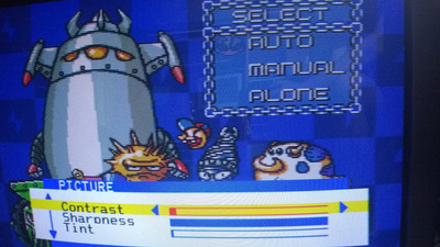
This is not the issue, nor the capacitors or resistors if the video looks good when adjusted low to avoid scan lines and blooming which is symptomatic of dying CRT.

When you turn up contrast, don't be confused with brightness this *should* will not do anything to that focus. When you adjust brightness, this will affect the focus if the CRT is shorted or gone soft which is in case with yours.

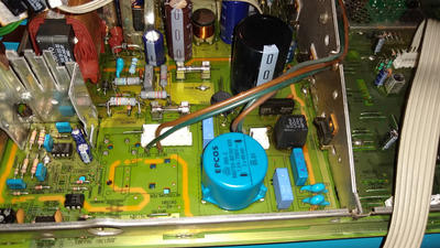
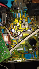
Contrast is adjusted via video signal to the cathode transistor amplifiers for R, G, and B guns so colors looks right. Brightness is around 1KV and is adjusted on main brightness knob on the flyback, also focus knob too.
This is done on the flyback transformer when all the settings in the user controls or knobs (at front) are centered. Then adjust the colors so they look correct on greyscale the CRT circuit if this have knobs, this is done with grey scale video signal from black, dark grey then about 9 bars of greys and finally white bar signal input via video input panel. Otherwise this is done by service mode (the ones with front panel buttons, no knobs) but you do not know the remote or buttons combinations to enter into service mode for this task.

I repaired CRT stuff back in the day, and knows this. All of the stuff we had went soft with age, some rarely dimmed with age if the CRT is very good quality. We didn't look back when we went to LCD technologies.

Greyscale video signal looks like this,

https://www.google.com/url?sa=i&url=https%3A% … QAAAAAdAAAAABAJ.

This is easiest way to correct your LCD and CRT, once done, then your image will look neutral and correct color every time and every color will not pop at you. Black should be black, the white should not be blown out and all the shades of grey visible and not blown out or tinted with any color. I don't adjust the colors as they are hard to judge while tv is in color mode and is incorrect way either. This why I base on grey scale video image to calibrate all my LCD and CRT if I have one.

Oh yeah, I did not turn the color knob down to get grey scale. which is incorrect way to do.

If you have hard time getting tint out of your grey scale image input from your dvd player, video generator etc, the CRT is tired or brand of LCD monitor or LCD TV has quality-wise is a trash.

Anyone that does have good CRT will greatly benefit from this grey scale adjustment method and extend your CRT life too so much. What kills CRTs quick are two evils: automatic kine adjustment, cannot be disabled, not all are bad, some are rather bad design, especially cheap one and Sony most especially. The other second evil is and brightness set too high (either or both on the flyback transformer and in user control). I set user-control brightness left of mid range around 40% or less as long is comfortable to view and no scan-line visible. During calibrating flyback bright knob (around 10% less from visible scan lines in the black area).

I repeat:

When calibrating internal settings using grey scale signal, all the user controls are set to mid range. Except LCD stuff, I use advanced user settings in the user menu using grey scale signal with brightness and contrast at mid range first then finish adjust to your comfortable settings after fixing the grey scale.

Cheers,

Great Northern aka Canada.

Reply 15 of 19, by alextpp7

User metadata
Rank Newbie
Rank
Newbie
Tiido wrote on 2021-07-02, 22:13:

The capacitor of interest is C61017, 100µF and 250V, on the +A rail in the service manual.

R61313 is the resistor to adjust to change the +A rail. When image shrinks the rail is rising and with it the HV and voltages derived from it (bigger HV = electrons move faster toward screen and spend less time in deflection field and deflect less due to it). I am not sure what is the safe range though, it cannot go too high without something dying in the process.

Hi, yesterday I played with the R61313 resistor. It doesn't do anything bad (at least for now), and if I set it to the maximum, it slightly increases the contrast without increasing the blur. Also while increasing the contrast, and I don't know why, it slightly stretches the picture horizontally. I can correct it in the service menu.
So your advice was good, I've got some more contrast from this resistor.

I guess that it regulates the filaments voltage isn't it ? For now I have no way to know what is the voltage and how many volts were the filaments increased by the resistor adjustment.

I really don't know if Grundig set the max of this resistor to a safe value. Do you think that I could change it for another one with a greater max value ?

Another thought, do you think if I would completely recap and change every transistors by new ones, could I get rid of the exaggerated blur ? Or should I live with in case the tube is really worn out ...

Last thing, when I increase the gamma in Retroarch, the picture gets a lot more brighter but the TV doesn't get more blur. I find this fact quite amazing and it gives me hope that there is something wrong in the TV and not just because it is worn out ...

Thank you

Reply 16 of 19, by mkarcher

User metadata
Rank l33t
Rank
l33t
alextpp7 wrote on 2021-07-23, 16:34:

Last thing, when I increase the gamma in Retroarch, the picture gets a lot more brighter but the TV doesn't get more blur. I find this fact quite amazing and it gives me hope that there is something wrong in the TV and not just because it is worn out ...

You should be aware that increasing the gamma does not make really bright pixels any brighter. It only increases the brightness of darker areas in the picture. A worn out CRT gets blurry in if a certain brightness level is exceeded (at the very "pixel" it is displaying). Your gamma solution makes the average pixels brighter, without making really bright pixels so bright that the image gets blurry.

Reply 17 of 19, by alextpp7

User metadata
Rank Newbie
Rank
Newbie
mkarcher wrote on 2021-07-23, 17:50:
alextpp7 wrote on 2021-07-23, 16:34:

Last thing, when I increase the gamma in Retroarch, the picture gets a lot more brighter but the TV doesn't get more blur. I find this fact quite amazing and it gives me hope that there is something wrong in the TV and not just because it is worn out ...

You should be aware that increasing the gamma does not make really bright pixels any brighter. It only increases the brightness of darker areas in the picture. A worn out CRT gets blurry in if a certain brightness level is exceeded (at the very "pixel" it is displaying). Your gamma solution makes the average pixels brighter, without making really bright pixels so bright that the image gets blurry.

Thanks for the info on gamma. I already read that it was something like you said but was not sure. It does make sense.
For this TV set, adjusting the gamma is a life saver. If I play with the contrast/brightness on the TV, then the gamma on the software side, I can get very acceptable results.

Reply 18 of 19, by Tiido

User metadata
Rank l33t
Rank
l33t
alextpp7 wrote on 2021-07-23, 16:34:

I guess that it regulates the filaments voltage isn't it ? For now I have no way to know what is the voltage and how many volts were the filaments increased by the resistor adjustment.

I really don't know if Grundig set the max of this resistor to a safe value. Do you think that I could change it for another one with a greater max value ?

Another thought, do you think if I would completely recap and change every transistors by new ones, could I get rid of the exaggerated blur ? Or should I live with incase the tube is really worn out ...

That resistor regulates the main power supply which has effect on HV, filament voltage and all other voltages dealing with the CRT itself. The range of that resistor is limited but I don't know how safe are the extremes, but at this point there's little to lose since the main fault is the tube itself and not any of the electronics.
No amount of capacitor and other things changes are going to help, actual tube swap would...

T-04YBSC, a new YMF71x based sound card & Official VOGONS thread about it
Newly made 4MB 60ns 30pin SIMMs ~
mida sa loed ? nagunii aru ei saa 😜

Reply 19 of 19, by alextpp7

User metadata
Rank Newbie
Rank
Newbie
Tiido wrote on 2021-07-23, 23:21:
alextpp7 wrote on 2021-07-23, 16:34:

I guess that it regulates the filaments voltage isn't it ? For now I have no way to know what is the voltage and how many volts were the filaments increased by the resistor adjustment.

I really don't know if Grundig set the max of this resistor to a safe value. Do you think that I could change it for another one with a greater max value ?

Another thought, do you think if I would completely recap and change every transistors by new ones, could I get rid of the exaggerated blur ? Or should I live with incase the tube is really worn out ...

That resistor regulates the main power supply which has effect on HV, filament voltage and all other voltages dealing with the CRT itself. The range of that resistor is limited but I don't know how safe are the extremes, but at this point there's little to lose since the main fault is the tube itself and not any of the electronics.
No amount of capacitor and other things changes are going to help, actual tube swap would...

Thanks again for the answer. So I guess I will use the TV like this, it sill doing great with gamma adjustments.