Kahenraz wrote on 2021-12-27, 15:46:
Can you clarify? I always thought that the value presented by the diode setting was just the resistance as a way to help you identify how closely is approaches a dead short. For example, my meter will beep on the diode setting at a very low resistance but still something higher than if I were to touch the two probes together. When it beeps, I then need to look at the meter and decide whether it's actually a short or just a result of the layout that it has a low resistance. I don't know the underlying layout of the board which is why I would like to reference a known working board to confirm if these values are normal.
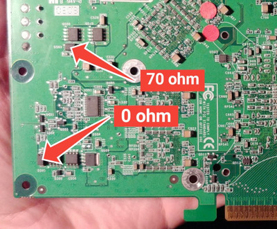
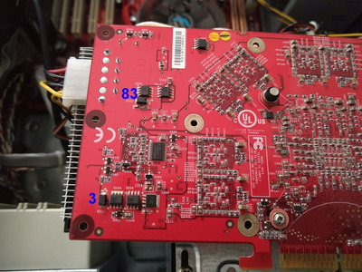
I measured across the diodes and got a similar result: 76/83 and 4/4 (measuring both ways).
I get different readings on these dioes depending on how I set my meter to measure resistance. This is why I noted specifically that I set my meter to 2000 ohms max. It's also a garbage meter so all of my readings are very imprecise. I'm more interested in the reading or diode D501 and to see how close it is to 0 on another board.
Different diode types will
Have different voltage drops
The meter will display the voltage drop value
Measuring the resistance isn’t useless but it isn’t the way or the primary way you should do it.
Just find all the resistors on that board and check their voltage drop if they all look like the same type and there are many of them and all read near the same they are probably all fine. If they all look the same and some read different those are probably bad
https://www.google.com/search?q=diode+voltage … mobile&ie=UTF-8
Your meter may use different voltages to measure resistance the diode only drops so many volts so at different voltages the percentage would be different. Like I said, reaistance is the wrong way to read a diode. You can note what it is though. And compare with others, but installed board components are likely also affecting the reading. it’s not a useless measurement just doesn’t tell us much.