VOGONS


First post, by Ltsyrek

User metadata
Rank Newbie
Rank
Newbie

Hello,

I have a problem with my IBM 5151 - after turning on, it displays jittery image (out of sync - like, I guess). The monitor behaves this way since about 10 years ago, though there were some brief, random moments when it displayed image correctly.
There is no difference in display quality when using different HGC cards/PCs. Also, leaving monitor turned on for longer time does not change anything. Same with increasing/decreasing brightness/luminocity as well as with using different CGA emulators.
What might be the cause of such behavior? It would be a waste to throw it away especially it was working ok sometimes...
Video showing symptoms
Thank you for your help!

Reply 1 of 6, by mkarcher

User metadata
Rank l33t
Rank
l33t
Ltsyrek wrote on 2022-01-29, 19:30:
Hello, […]
Show full quote

Hello,

I have a problem with my IBM 5151 - after turning on, it displays jittery image (out of sync - like, I guess). The monitor behaves this way since about 10 years ago, though there were some brief, random moments when it displayed image correctly.
There is no difference in display quality when using different HGC cards/PCs. Also, leaving monitor turned on for longer time does not change anything. Same with increasing/decreasing brightness/luminocity as well as with using different CGA emulators.
What might be the cause of such behavior? It would be a waste to throw it away especially it was working ok sometimes...
Video showing symptoms
Thank you for your help!

The good news: Horizontal sync is working fine on the monitor. The horizontal stuff is the scary stuff that works with moderately high voltages (hundreds of volts) and is coupled to the anode voltage generation (around 13000 volts). Your problem is that the vertical oscillator is not syncing correctly. Most CRT monitors have a "vertical hold" adjustment pot. If that pot is slightly off, you will get a rolling image. If the setting of that pot is completely off, you might get the symptom shown in your video. My guess is that the vertical hold adjustment pot lost contact and needs cleaning or replacement. Of course, other causes are also possible.

In the IBM 5151 Monochrome Display, the vertical hold adjustment is VR401. This YouTube video called "How to repair an IBM 5151 Monitor" points to the Vertical Hold ("V-Hold") pot at around 10:15 (the link is timestamped).

Reply 2 of 6, by Ltsyrek

User metadata
Rank Newbie
Rank
Newbie
mkarcher wrote:

The good news: Horizontal sync is working fine on the monitor. The horizontal stuff is the scary stuff that works with moderately high voltages (hundreds of volts) and is coupled to the anode voltage generation (around 13000 volts). Your problem is that the vertical oscillator is not syncing correctly. Most CRT monitors have a "vertical hold" adjustment pot. If that pot is slightly off, you will get a rolling image. If the setting of that pot is completely off, you might get the symptom shown in your video. My guess is that the vertical hold adjustment pot lost contact and needs cleaning or replacement. Of course, other causes are also possible.

In the IBM 5151 Monochrome Display, the vertical hold adjustment is VR401. This YouTube video called "How to repair an IBM 5151 Monitor" points to the Vertical Hold ("V-Hold") pot at around 10:15 (the link is timestamped).

It seems that you may be right. Probably pots are broken - after removing the glue and moving them around i can get maximum values of:
V-hold - 93kohm (should be 100-250kohm if I read correctly)
V-height - 235kohm (should be 250kohm)
V-linearity -49kohm (should be 50kohm)
The problem still persists at these values. I' ll try to clean them or get new pots and replace them.

Reply 3 of 6, by mkarcher

User metadata
Rank l33t
Rank
l33t
Ltsyrek wrote on 2022-02-01, 17:49:
It seems that you may be right. Probably pots are broken - after removing the glue and moving them around i can get maximum valu […]
Show full quote

It seems that you may be right. Probably pots are broken - after removing the glue and moving them around i can get maximum values of:
V-hold - 93kohm (should be 100-250kohm if I read correctly)
V-height - 235kohm (should be 250kohm)
V-linearity -49kohm (should be 50kohm)
The problem still persists at these values. I' ll try to clean them or get new pots and replace them.

Your meter measures resistance by applying some voltage to the circuit and measuring how much current the circuit draws at that voltage. It assumes that all of the current it detects flows through the resistor you want to measure. If the resistor is mounted inside the a circuit, some current might flow other paths than straight through the resistor you want to measure. So low readings of resistance are often expected when you measure in circuit. I am very confident that V-height and V-linearity are OK. V-hold should be 0..250K, according to the schematics in the IBM PC Technical Reference manual, but as both ends are connected to the vertical deflection control chip, you can't exclude some current flowing through that chip. If the resistance measured at the V-hold pots changes smoothly when you turn it, the pot is likely OK.

If you have a capacitor checker, checking the electrolytic caps C405, C409 and C410 might make sense. No need to check C408. If that cap is dead, you will get less deflection (black bars at the top and bottom), but the monitor will still sync correctly.
Reply 4 of 6, by Ltsyrek

User metadata
Rank Newbie
Rank
Newbie

Thank you for the advice, I' ll remove the pots and try to set their value outside of the circuit then. I guess that trying to set these pots with the monitor turned on is not really a safe option (correct me if I am wrong). I do not have any tools for discharging crts, so now I am just waiting for several days after every turning it on for a bit more of safety 😄.
Yes, the pot resistance change smoothly when I turn them, and it holds it.
I do not have a capacitor checker, but I can jutr try to get new capacitors and replace them if manipulating the V-hold pot would not help.

Reply 5 of 6, by mkarcher

User metadata
Rank l33t
Rank
l33t
Ltsyrek wrote on 2022-02-02, 21:10:

Thank you for the advice, I' ll remove the pots and try to set their value outside of the circuit then. I guess that trying to set these pots with the monitor turned on is not really a safe option (correct me if I am wrong). I do not have any tools for discharging crts, so now I am just waiting for several days after every turning it on for a bit more of safety 😄.

Wait a second! The values in the schematic (250k or 50k) is not what you should set them to. That value indicates the model of the pot, i.e. the maximum value you can set it to.

It makes no sense to set the pots out-of-circuit, because you don't know what you need to set them to. The idea is that you run the monitor with the cover removed and set the pots while a picture is displayed. You should use a sufficiently isolated tool, ideally a wood or plastic tool to set them while the monitor is running. You do definitely not need a "CRT discharge tool". This tool is meant to discharge the anode voltage, but as long as you don't disconnect the big wire from the transformer to the rubber cup at the tube, the anode voltage is safely isolated and there is no way to touch it at all. Nevertheless, while you shouldn't be scared by the voltages inside the monitor, working carefully and keeping distance from the PCB while the monitor is powered on (and some minutes later) is a good idea.

Reply 6 of 6, by Ltsyrek

User metadata
Rank Newbie
Rank
Newbie
mkarcher wrote on 2022-02-02, 22:57:

Wait a second! The values in the schematic (250k or 50k) is not what you should set them to. That value indicates the model of the pot, i.e. the maximum value you can set it to.

It makes no sense to set the pots out-of-circuit, because you don't know what you need to set them to. The idea is that you run the monitor with the cover removed and set the pots while a picture is displayed. You should use a sufficiently isolated tool, ideally a wood or plastic tool to set them while the monitor is running. You do definitely not need a "CRT discharge tool". This tool is meant to discharge the anode voltage, but as long as you don't disconnect the big wire from the transformer to the rubber cup at the tube, the anode voltage is safely isolated and there is no way to touch it at all. Nevertheless, while you shouldn't be scared by the voltages inside the monitor, working carefully and keeping distance from the PCB while the monitor is powered on (and some minutes later) is a good idea.

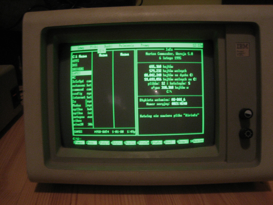
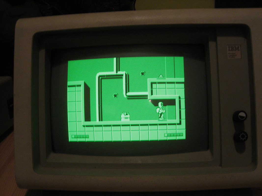
A moment ago I have set V-hold when the monitor was turned on and... you were absolutely right about that pot setting. Success!
There is a beautiful image (the photos are a bit blurry though).
IMG-1048-1.jpg
IMG-1049-1.jpg

Thank you so much for helping! 😄 That 5151 has been lying broken for over ten years in closet and probably I would never find a solution. Now I can replay my childhood games...