VOGONS


First post, by Joosemachine

User metadata
Rank Newbie
Rank
Newbie

Hi all,

I'm hoping some of the voodoo guru's on here can help me with diagnosing the problem(s) with this voodoo2 card I picked up recently. It has the fairly common symptom of being detected as a PCI multimedia device, but failing the Mojo test. Here are the results of the test:

IMG_20230306_205900.jpg
Filename
IMG_20230306_205900.jpg
File size
1.89 MiB
Views
1584 views
File license
CC-BY-4.0

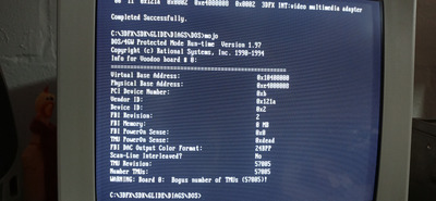
The first issue is obviously the FBI memory is 0 mb, and then when it tries to initialise the TMUPowerON sense, it reads 0xdead! That cant be good! The test then detects 57005 TMU's, which obviously isnt right...
The logs say the following:

sst1Init Routines: InitCode $Revision: 8 $
sst1InitMapBoard(): BoardsInSystem = 1
sst1InitMapBoard(): vAddr:0x10400000 pAddr:0xe4000008 Dev:0xb Board:0
sst1InitRegisters(): Setting TREX-to-FBI FIFO THRESHOLD to 0x8...
sst1InitRegisters(): Setting PRELIM FT-CLK delay to 0x8...
sst1InitDacDetect(): Entered...
sst1InitDacDetectICS(): Entered...
dacWr(0x7,0xb)
dacRd(0x5,0x79)
dacRd(0x5,0x2e)
dacWr(0x7,0x1)
dacRd(0x5,0x55)
dacRd(0x5,0x49)
dacWr(0x7,0x7)
dacRd(0x5,0x71)
dacRd(0x5,0x29)
sst1InitDacDetectICS(): Exiting...
sst1InitRegisters(): Storing TREX0INIT0=0x5441
sst1InitRegisters(): Storing TREX0INIT1=0xf420
sst1InitRegisters(): Storing TREX1INIT0=0x5441
sst1InitRegisters(): Storing TREX1INIT1=0xf420
sst1InitRegisters(): Storing TREX2INIT0=0x5441
sst1InitRegisters(): Storing TREX2INIT1=0xf420
sst1InitSetGrxClk(): Entered...
dacWr(0x7,0xe)
dacRd(0x5,0x0)
dacWr(0x4,0xa)
dacWr(0x5,0x7b)
dacWr(0x5,0x6c)
dacWr(0x4,0xe)
dacWr(0x5,0x0)
sst1InitSetGrxClk(): Resetting TMUs after clock change...
sst1InitResetTmus(): Could not reset TMUs...

I dont really know how to read this, but it seems to me from this that the DAC is working (setting registers, doing read/writes etc) but then it obviously fails when it tries to talk to the TMU's.

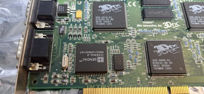
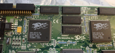
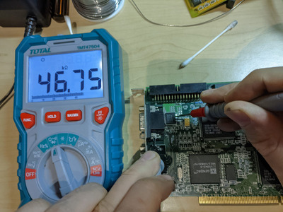
Taking a look at the card, I only notice one problem - it looks like R51 is missing, which I'm sure is causing at least part of the issue:

IMG_20230306_210517.jpg
Filename
IMG_20230306_210517.jpg
File size
1.51 MiB
Views
1584 views
File license
CC-BY-4.0

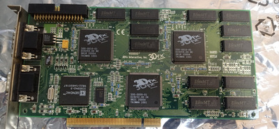
I dont know what brand my card is, but the PCB revision is 600-0027-02-B. Looking at the schematic found here on Vogons for the INNOVISION_MIGHTY_3DII_V3, I see that resistor's value is 10R, but the innovision is revision 600-0027-03. Do you think its safe to use the 10R resistor on my card?:

V2_INNOVISION_MIGHTY_3DII_V3_TOP.png
Filename
V2_INNOVISION_MIGHTY_3DII_V3_TOP.png
File size
614.43 KiB
Views
1584 views
File license
CC-BY-4.0

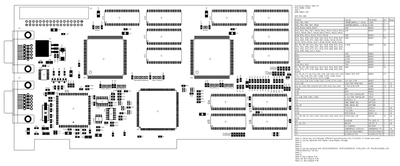
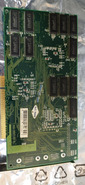
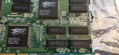
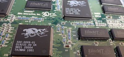
So.. could the missing R51 be responsible for all the issues? I see there are quite a lot of "missing" resistors on the PCB, but it looks like they were never there because the pads are still perfectly clean/unused, whereas R51 looks like there was something soldered on there.. Here are some more pics of the rest of the card:

IMG_20230306_210427.jpg
Filename
IMG_20230306_210427.jpg
File size
1.84 MiB
Views
1584 views
File license
CC-BY-4.0
IMG_20230306_210443.jpg
Filename
IMG_20230306_210443.jpg
File size
464.86 KiB
Views
1584 views
File license
CC-BY-4.0
Last edited by Joosemachine on 2023-03-06, 20:02. Edited 1 time in total.

Reply 1 of 15, by Joosemachine

User metadata
Rank Newbie
Rank
Newbie
IMG_20230306_210642.jpg
Filename
IMG_20230306_210642.jpg
File size
1.43 MiB
Views
1578 views
File license
CC-BY-4.0
IMG_20230306_210642.jpg
Filename
IMG_20230306_210642.jpg
File size
1.43 MiB
Views
1578 views
File license
CC-BY-4.0
IMG_20230306_210628.jpg
Filename
IMG_20230306_210628.jpg
File size
1.42 MiB
Views
1578 views
File license
CC-BY-4.0

Attachments

Reply 2 of 15, by Imperious

User metadata
Rank Oldbie
Rank
Oldbie

If the pads are clean likely there was nothing there in the first place. R51 is a 10 ohm 0603 size resistor so replace that first and take it from there.
I'd also check the pins on the TMU's and FBI are not loose. Use a scalpel blade for that.
Good luck.

Atari 2600, TI994a, Vic20, c64, ZX Spectrum 128, Amstrad CPC464, Atari 65XE, Commodore Plus/4, Amiga 500
PC's from XT 8088, 486, Pentium MMX, K6, Athlon, P3, P4, 775, to current Ryzen 5600x.

Reply 3 of 15, by sdz

User metadata
Rank Member
Rank
Member

R51 needs to be present, it's quite important. Actual value is not that critical, 10-22R should be fine, as it's just a series termination resistor.
For a quick test you can replace it with a blob of solder and see if the card works.

Reply 4 of 15, by Joosemachine

User metadata
Rank Newbie
Rank
Newbie

Thanks so much @imperious and @sdz for your help, I'll try get hold of a replacement resistor to fix it. Quick (and potentially dumb) question: I dont know much about resistors - is a 10r resistor 10Ω or 10kΩ or what? I am seeing 10kΩ on various sites in this size, but 10Ω seems like a very low value..

Reply 9 of 15, by Joosemachine

User metadata
Rank Newbie
Rank
Newbie

Just an update on this, and hoping to get some more help..

I replaced resisitor 51 with the correct part - didnt make any difference to mojo's diagnostic results.. so I poked around a bit more and found 1 resistor on RA9 that was open circuit, so I replaced the array with a suitable replacement and confirmed that all the connections through the array are now good, but again no change to mojo's result.. I have also been browsing this and other forums trying to find if anyone has been able to fix the "0xdead" TMU error I have and it doesnt look hopeful.. all of those threads tend to go quiet with no-one posting a successful repair. So my questions at this point basically are:

Does anyone have an idea where I should look next with diagnosing this card? I was thinking trying to check if the TMU is getting power, but not sure which pin on the TMU is power?
And has anyone done(or know of) a successful repair on a voodoo card with a "0xdead" message? I'm beginning to think that maybe "0xdead" does actually mean the TMU is dead?

Reply 10 of 15, by sdz

User metadata
Rank Member
Rank
Member

TMU power pins are: 15 27 31 43 58 73 78 96 109 116 128 140 143 153 163 173 183 187 203
The RAMDAC should provide a clock to the TMU, you can check TMU pin 186 if you have an oscilloscope. You could also check TMU pin 208, RESET. This should be directly connected to FBI pin 197.
Also, gently poke all the FBI and TMU pins and see if they're actually soldered. This is really important to check, although they may look fine, they can be detached from the PCB.

Reply 13 of 15, by Imperious

User metadata
Rank Oldbie
Rank
Oldbie

I'd take a look at the right TMU. 2 Pins about number 194 look like they are shorted, but it coud just be a speck of dust.

Atari 2600, TI994a, Vic20, c64, ZX Spectrum 128, Amstrad CPC464, Atari 65XE, Commodore Plus/4, Amiga 500
PC's from XT 8088, 486, Pentium MMX, K6, Athlon, P3, P4, 775, to current Ryzen 5600x.

Reply 14 of 15, by Joosemachine

User metadata
Rank Newbie
Rank
Newbie

Hi all. So I tried to test the voodoo with a friend's oscilloscope, but I don't really know how to use one.. I did manage to get it to show some signal next to the crystal and also in a few places (like R153,R154,R155). I also thought I spotted a clock signal around pin 186 on TMU 0, but it didn't seem to also be there on TMU 1.. so that is probably the issue. I also noticed this: I saw someone else on vogons testing the capacitance here :

IMG-20230506-WA0017.jpg
Filename
IMG-20230506-WA0017.jpg
File size
189.85 KiB
Views
1113 views
File license
CC-BY-4.0

But on my card it only goes to to 50k or so ohms, but I think this is meant to go up to 300, right?

Reply 15 of 15, by meljor

User metadata
Rank Oldbie
Rank
Oldbie

Capacitors can not be measured in circuit...

asus tx97-e, 233mmx, voodoo1, s3 virge ,sb16
asus p5a, k6-3+ @ 550mhz, voodoo2 12mb sli, gf2 gts, awe32
asus p3b-f, p3-700, voodoo3 3500TV agp, awe64
asus tusl2-c, p3-S 1,4ghz, voodoo5 5500, live!
asus a7n8x DL, barton cpu, 6800ultra, Voodoo3 pci, audigy1