Reply 140 of 152, by feipoa

- Rank
- l33t++
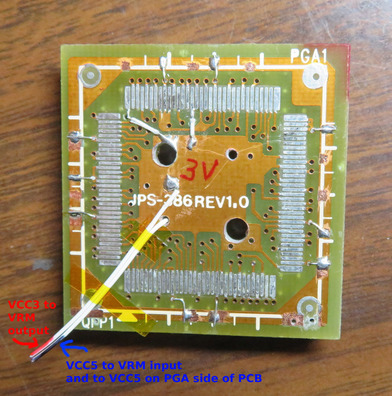
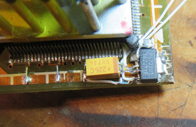
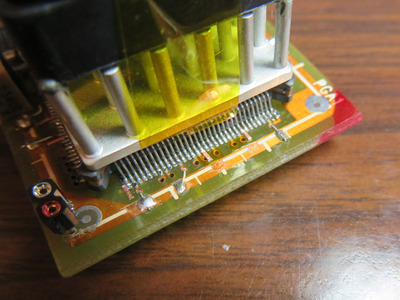
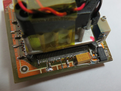
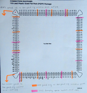
The selected locations of these decoupling caps are shown in the following image. Also shown are approximate locations used to connect the upper ground ring to the lower ground ring:
For those wanting to replicate this design, a rough BOM would look something like this:
a) a QFP132 to PGA132 interposer board, ideally one which space for the regulator and convenient GND points
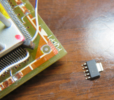
b) TPS72501DCQR voltage regulator, SOT223 package
c) 22 uF tantalum capacitor. I'm using 2312 size because that's what I had.
d) 1 uF or 10 uF ceramic capacitor. I'm using 1 uF in 0805, X7R.
e) narrow 1210 caps for the 5V plane. I'm using 2x 100 nF and 2x 10 nF because that's what I had.
f) 11x 100 nF ceramic capacitor, 0603 size, X7R. I'm using 25 or 50 V. 10 are for the QFP leads, the 11th one is for the 5V section near the fan header
g) 124 K-ohm resistor, 0805 size. I'm using RK73H2ATTD1243F.
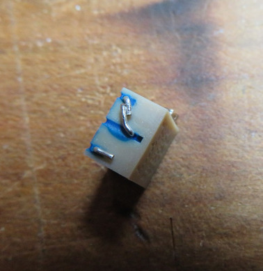
h) 500 K-ohm Bourns trimmer, 12-turn. 3269X-1-50HLF. Only Mouser had stock last I checked.
i) 25x25x6 mm fan, 5V, 2.2 CFM - if you are using the stock 25 mm heatsink. MF25060V2-1000U-A99
j) epoxy, for fan and trimmer mounting
k) copper tape, for routing the decoupling caps to the QFP leads
l) solder paste. I'm using TS391AX with the finest tip, SMDC-25G
m) 28 AWG, for Vin and Vout only. Also for connecting the 5V plane to itself
n) 30 AWG, for all other connections to the voltage regulator
o) male-to-female machine pin header, for fan
p) Dremel, extra narrow drill bit set, enamel scrapping tool (scalpel), hot air station, soldering iron w/fine tips, etc.
q) heatsink, only if you aren't using the IBM standard 25 mm one. You can probably fit up to a 35 mm heatsink and still have room for the trimmer. I have a 32 mm heatsink I was going to go with if I was using a BL3 CPU without a factory heatsink still mounted.
r) kapton tape, for use as an electrical insulator
s) time, patience, and a steady hand.
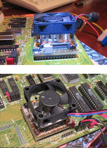
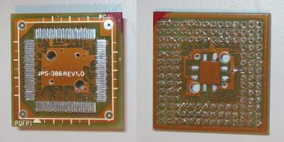
First up, remove the 386DX from your interposer using hot air:
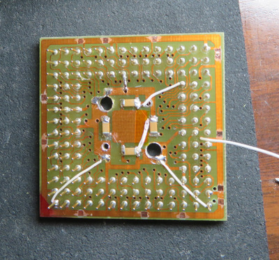
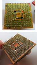
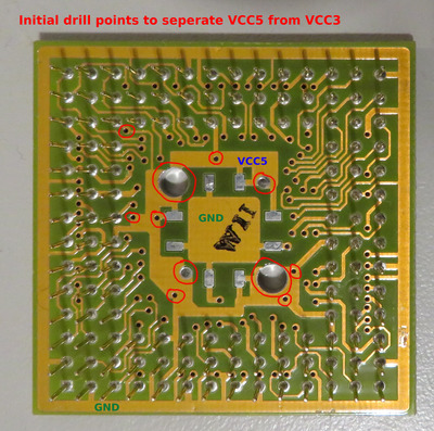
Then drill out the 11 holes and vias which connect the PCB's bottom 5V plane from the PCB's top 5V plane. We will be leaving the bottom plane as 5V and making the top plane variable, VCC3.
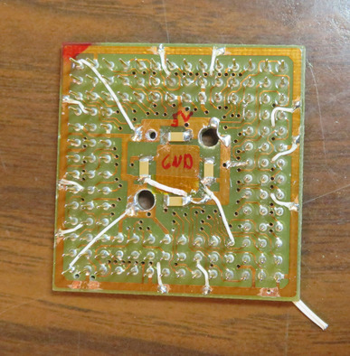
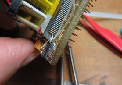
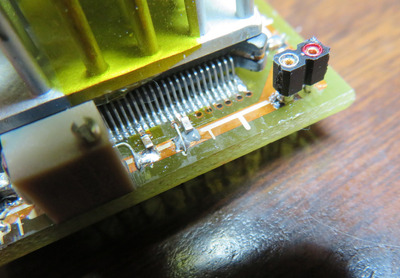
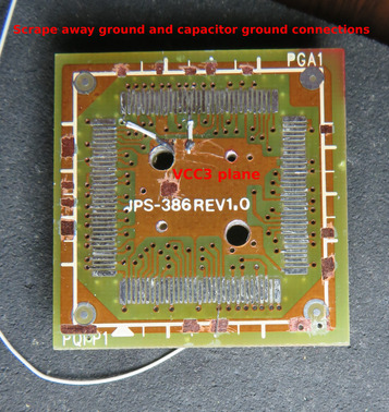
You will want to reconnect two of the QFP leads as shown below. Start scrapping away the enamel in select locations around the top ground ring, which is used for caps and ground connections. See:
Plan your life wisely, you'll be dead before you know it.