VOGONS


First post, by candle_86

User metadata
Rank l33t
Rank
l33t

So i got a compaq board, model 010630-101

not sure what it is, but it has a 24in ATX connector, whats odd is it is socket 370 so im guessing its not a standard pinout, anyone know

Reply 1 of 12, by dionb

User metadata
Rank l33t++
Rank
l33t++
candle_86 wrote on 2020-05-25, 14:46:

So i got a compaq board, model 010630-101

not sure what it is, but it has a 24in ATX connector, whats odd is it is socket 370 so im guessing its not a standard pinout, anyone know

Yep, it's a Compaq proprietary pinout, most definitely not regular ATX 2.x. There's also a version with proprietary AUX connector next to it just to complicate matters a bit further (used on the boards in AP550 workstations)

I have two boards with it here, with PSU. If you intend to try to adapt your own cable I can see if I can figure out the pinout.

Reply 2 of 12, by PC Hoarder Patrol

User metadata
Rank l33t
Rank
l33t

FYI, here's the correct PSU details

Compaq Deskpro EN Power Supply
Series: PDP-110
Compaq Part Number: 161071-001
Compaq Spare part number: 176764-001
Compatible Compaq Models: Business Desktop D315, EN Desktop

Reply 3 of 12, by candle_86

User metadata
Rank l33t
Rank
l33t

Ty and yes I'm going to order a 20 to 24pin adapter, tested with a normal 24pin for fitment and it slides in fine, so next is to rewire one. These boards are dirt cheap right now but are 815e boards so agp is present.

If I wire up an adapter I should be able to make it work.

Reply 4 of 12, by dionb

User metadata
Rank l33t++
Rank
l33t++

Looks like someone else already did the effort:
https://pinouts.ru/Power/compaq_24p_power_pinout.shtml

Double-check continuity between RTN (=GND) and voltage pins and convenient points on the board, but it looks about right.

Reply 5 of 12, by candle_86

User metadata
Rank l33t
Rank
l33t
dionb wrote on 2020-05-26, 13:40:

Looks like someone else already did the effort:
https://pinouts.ru/Power/compaq_24p_power_pinout.shtml

Double-check continuity between RTN (=GND) and voltage pins and convenient points on the board, but it looks about right.

Will do, I did find the psu's but they are all square so it's my only option

Reply 7 of 12, by candle_86

User metadata
Rank l33t
Rank
l33t
dionb wrote on 2020-05-26, 13:40:

Looks like someone else already did the effort:
https://pinouts.ru/Power/compaq_24p_power_pinout.shtml

Double-check continuity between RTN (=GND) and voltage pins and convenient points on the board, but it looks about right.

would you be willing to take a quick look at your psu and tell me which one is correct, i don't want to fry the board

even just a picture of both sides of the connector i can use the psu colors that compaq used to tell what they do

Reply 8 of 12, by PC Hoarder Patrol

User metadata
Rank l33t
Rank
l33t

Hopefully @dionb can confirm for you, but meantime if you do a Google search for "ps-6201-1c pinout" and look at the images returned you'll see a Polish forum http://www.elektroda.pl/rtvforum has done some work on this already

Reply 9 of 12, by candle_86

User metadata
Rank l33t
Rank
l33t

That helped my 2nd link seems to be what they are working off.

My first thought is to go with the 2nd and leave pins 11,12 and 24 not connected and assume ,5v aux is 5vsb

Reply 10 of 12, by CATSOFT

User metadata
Rank Newbie
Rank
Newbie

Hello, have you managed to use a normal ATX power supply? I have a board, and I want to test/use it. Seems like the correct pinout is in your second link, but the board wont power on. Thank You!

52_1241193446.jpg

Reply 11 of 12, by CATSOFT

User metadata
Rank Newbie
Rank
Newbie

So I got the original power supply, and I'm making a reverse engineering of the power startup voltages. It works with an normal 20pin ATX power supply, but needs some bodge wires. For some reason, it needs the extra 3V3 Aux, but that can be tied to Power 3V3, but wont power on the PSU. The On/Off pin is inverse to the ATX standard, normally an ATX has 5V on that pin, and when you short it to ground, the PSU powers on, this is reverse, when off, 0V. When the mainboard supply 5V on that pin, the PSU powers on. So with an normal ATX, it powers on only if you short manually the On/Off pin to ground, tie the 3V3 Aux to 3V3 Power, and stays on only if you keep the short. For some reason, the CPU fan doesn't work, the ground pin on the fan is connected to the Fan Sink on the power connector, if you short it to ground, then the CPU Fan works. But this behavior is also with the original PSU, even though the PSU has all the wires, no CPU or PSU fan work, so still need to find out what does the Fan Sink connects to in the PSU, and why not ground. With the original PSU the mainboard powers on at AC connect, and you use the power button to stop the PC (or start, afterwards). This is weird.
I write this, for people who need this.

Reply 12 of 12, by CATSOFT

User metadata
Rank Newbie
Rank
Newbie

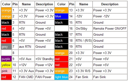
So, opening the PSU reveals that indeed, 3v3 Aux is just derived from 5V Aux, so with just a simple 3v3 LDO mounded on the mainboard and an transistor to invert the signal for power on, you can just turn this into a mainboard working on a normal ATX power supply. The fan on the other hand, is very convoluted. The upper pinout is wrong on 2 pins. Pin 20 is unused, as a normal ATX, and was the former -5V that was used in normal AT PSU, on the mainboard is not connected to anything, measures nothing. Pin 8 is connected in the PSU to a FAN On designation, so there are 3 Pins dedicated to controlling the CPU and PSU Fan . I think that I fried something on the mainboard when I connected a normal ATX PSU, as on a regular ATX PSU that pin provides 5V for Power OK signal to the mainboard, so on my mainboard the fans don't work. I tried to short that pin to 3v3, 5V and GND, but nothing happened. I followed the Fan sink pin that goes to a power transistor that when on, connects it to a dedicated -5V supply. So from my understanding, the mainboard powers on the fans on pin 8, regulates their speed based on temperature (the controller that drives the transistor in the PSU has an temperature probe on the heatsink in the PSU, and I assume one on the mainboard) on pin 12, and drives the fans on pin 24, that is linearly the ground (minus) of the fans. I didn't see any temperature monitoring in the bios. So, in short, there are 2 ways for ATX on this mainboard. A more sophisticated way in witch you can use the power button and soft start/shutdown the system as a normal ATX PSU, by mounting a 3V3 LDO from pin 9 to pin 11 and GND, and a transistor to invert pin 16 signal, and short pin 24 to GND for the CPU Fan to work. Or simple way in witch you use a normal switch to power on the system and shutdown like a normal AT PSU, just bridge pin 11 to pin 23 for 3v3 , pin 24 to GND for Fan, and use the switch on pin 16 to GND to power on the system.