VOGONS


No CRT Emulation? Why!?

Topic actions

Reply 160 of 177, by leileilol

User metadata
Rank l33t++
Rank
l33t++

I dont' think reshade scales up from a buffer so CRTs on that are probably going to be moirey...

apsosig.png
long live PCem

Reply 161 of 177, by Deffnator

User metadata
Rank Member
Rank
Member
leileilol wrote on 2023-05-06, 21:54:

I dont' think reshade scales up from a buffer so CRTs on that are probably going to be moirey...

Crosire is working on that if i remember, but that means a visit to reshade forums, also there is the addon version.

Reply 162 of 177, by VileR

User metadata
Rank l33t
Rank
l33t

Hm, how about RetroArch's own ffmpeg core then? Viable?
My thoughts are along the lines of taking arbitrary video sources of the 'correct' resolution (say, real hardware RGB captures), applying a shader on playback, then capturing that using OBS or somesuch.

[ WEB ] - [ BLOG ] - [ TUBE ] - [ CODE ]

Reply 163 of 177, by Mr_Blastman

User metadata
Rank Member
Rank
Member
VileR wrote on 2023-05-08, 18:18:

Hm, how about RetroArch's own ffmpeg core then? Viable?
My thoughts are along the lines of taking arbitrary video sources of the 'correct' resolution (say, real hardware RGB captures), applying a shader on playback, then capturing that using OBS or somesuch.

Capturing Retroarch through OBS sucks quite a bit. Despite being 1:1 capture, OBS produces a ton of artifacting and image distortion during the capture. I've even seen VGA emulation converted by OBS into vertical scanlines!

Here's an example of what I mean, where I used a special core inside Retroarch that allows me to capture any window within Windows called "WindowCast"(which is useful to apply MegaBezel shaders and effects to a pixel art Steam game ) and apply my VGA monitor shaders:

https://www.youtube.com/watch?v=6kPeaAnuL8I

Those vertical scanlines are not present on my monitor, at all, when I am playing. Also, the shadow mask is visible(80s VGA monitor being emulated) on my screen but not on the capture.

I haven't tried the built in capture in a while, but probably should. That kind of defeats the purpose, however, for being able to stream gaming on Retroarch.

Reply 164 of 177, by crusher

User metadata
Rank Member
Rank
Member

I don't have one on my own but there are people swearing on such devices called upscalers.
The main purpose is to upscale low resolutions of old video consoles/pc for high resolution TVs (Full HD up to 4K).
As a side effect many also offer CRT filters/shaders and such things.
What I read it seems to pretty work well.

Recent devices are: Retrotink 4K, OSSC Pro, Morph 4K for example.
An older device but very popular is called "Framemeister".

Reply 165 of 177, by midicollector

User metadata
Rank Member
Rank
Member

It’d be interesting conceptually to do an actual simulation of the beam, glass and shadow mask. Not for any actual practical use or purpose, but just as a fun simulation to make, especially if you tried to go really far on the physics accuracy.

Reply 166 of 177, by Jo22

User metadata
Rank l33t++
Rank
l33t++
midicollector wrote on 2024-04-13, 05:59:

It’d be interesting conceptually to do an actual simulation of the beam, glass and shadow mask. Not for any actual practical use or purpose, but just as a fun simulation to make, especially if you tried to go really far on the physics accuracy.

Raytracing!! 😃

For such things, vector calculations are needed.
An GPU, FPU or SIMD (MMX/SSE/AVX) could greatly improve performance here.

"Time, it seems, doesn't flow. For some it's fast, for some it's slow.
In what to one race is no time at all, another race can rise and fall..." - The Minstrel

//My video channel//

Reply 167 of 177, by appiah4

User metadata
Rank l33t++
Rank
l33t++
Jo22 wrote on 2024-04-13, 07:46:
Raytracing!! 😃 […]
Show full quote
midicollector wrote on 2024-04-13, 05:59:

It’d be interesting conceptually to do an actual simulation of the beam, glass and shadow mask. Not for any actual practical use or purpose, but just as a fun simulation to make, especially if you tried to go really far on the physics accuracy.

Raytracing!! 😃

For such things, vector calculations are needed.
An GPU, FPU or SIMD (MMX/SSE/AVX) could greatly improve performance here.

Even with such I do not think anything below a 4K monitor would have the pixel density required to make the effect work..

Reply 168 of 177, by Mr_Blastman

User metadata
Rank Member
Rank
Member

The closest yet to a Tandy CM-5 Color RGB monitor:

3Rc8PAY.jpg

sM7qLle.jpg

Particular problems with emulating this CRT properly have been the staggered slot mask pattern of the phosphors. Contrary to general public belief of 80s CRTs--that they must have horizontal scanlines, this RGB tube has prominent, visible vertical lines that slice through the image, as well as the horizontal scan pattern. Now, most PC monitors don't have any scanlines at all, but because the dot pitch of this tube is so high @ ~.66, the granularity of the image on the real device is quite perceptible.

The Mega Bezel shader suite with Retroarch has allowed me to come close, however the core I was using, Dosbox-Core, only rendered images in 640x400, and not 320x200, which caused problems with achieving granularity. So hurdles overcome since the last update:

1) Staggered Slot mask implemented, which requires 1440+ on the vertical. (thanks to rucukokt for the screenshots of his tube, which match mine)
2) Switched to Dosbox-Pure core, which properly outputs DOS at adequate lower resolutions, at 640x200 for Text prompt mode and 320x200 for most games.

DOS text was a huge challenge to overcome, as the graininess simply was not matching the actual display. Now it comes quite close. Finally the Thexder has a proper "metallic" feel to the image, and other games and DOS text look even closer to the real display. Also notice the phosphor glow "trail." The real tube has this.

More refining is needed, but this is the closest yet to a staple, classic CRT tube used to a wide swath of mid to late 1980s PC gamers.

Reply 169 of 177, by Trypticon

User metadata
Rank Newbie
Rank
Newbie

Pitches from 0.4-0.52 are common for CGA monitors, once you come into 0.6 range, I would think that goes into Tv territory.
Once a pitch is stated to be below 0.4, you can be fairly certain it uses a dot mask, at least for 80's/early 90's monitors of typical size (since NEC/LG re-introduced low pitch slot mask later in a limited scope).
I do wonder if there were still some monitors with really high pitch dot masks though. In the TV sector, these seem to be basically gone by the early 80's.

With a high pitch CRT, the scanlines seem less prominent, but that's not the only factor. E.g. before I did a focus adjustment on the used Eizo Multisync (0.28 mm pitch) I acquired sometime ago, there were large areas in the middle of the screen that seemed scanline free 😉

Reply 170 of 177, by Mr_Blastman

User metadata
Rank Member
Rank
Member

The colors were off in my previous implementation. I have spent hours upon hours tweaking the virtual CRT shader color dials to get closer to my real CM-5 monitor. For those unaware, the CM-5 had a special knob in the back of the monitor that let you dial in the color brown to various intensities. This had a remarkable effect on how images looked. On mine, the Thexder title screen would have a golden hue. In King's Quest IV the title screen would also be quite golden.

I am getting closer:

jvpLYTO.jpg

2tEa92i.jpg

FERIylj.jpg

The blues are not as deep. The greens are lighter and brighter. The reds are powerful and broad and the entire image output is warmer. Ghosting also looks appropriate and good.

Obsessed? You bet! Someone has to do this. 😀

I feel my VGA implementation is already quite great.

QuCuKgS.jpg

The goal with VGA being to capture that of a late 80s VGA monitor.

Reply 171 of 177, by Mr_Blastman

User metadata
Rank Member
Rank
Member
Trypticon wrote on 2024-05-26, 14:08:

With a high pitch CRT, the scanlines seem less prominent, but that's not the only factor. E.g. before I did a focus adjustment on the used Eizo Multisync (0.28 mm pitch) I acquired sometime ago, there were large areas in the middle of the screen that seemed scanline free 😉

The only CRTs I recall seeing actual scanlines on were the early 80s IBM Color Monitors, and later 90s era Super VGA monitors when running in lower resolutions such as 640x480. My Viewsonic G771(I think) aperture grille display did this, and was quite a nice monitor for the period.

Reply 172 of 177, by mdrejhon

User metadata
Rank Newbie
Rank
Newbie

Very impressive!

Long term, I'd love the temporal element to be added to current CRT simulators. They only simulate spatially, with only a bare-bones BFI sometimes.

Basically, "next generation BFI" is a more true electron beam simulation (for 240, 360 and 480Hz OLEDs). Basically an advanced shingled overlapped rolling scan BFI, like a single frame of a 480fps high speed video of a CRT tube, but played back real time to a 480 Hz monitor. You emulate 1/480sec of electron beam (including 1/480sec of phosphor decay etc), like software-generated stillframe of a high speed video of a CRT.

The more digital Hz per analog Hz (e.g. 480Hz to emulate 60Hz CRT), the easier it is to emulate all the temporal behaviors of CRT (flicker, parallelogramming during eyeroll, phosphor fade, zero motion blur).

As creator of TestUFO... Also, the science of BFI is more easily understood with higher Hz (if you have a 240Hz screen, see TestUFO Variable Persistence BFI). And I can even emulate CRT 30fps at 60Hz in software (including javascript) -- see TestUFO Double Image Effect.

BTW, as founder of Blur Busters / TestUFO, I helped Retrotink add BFI to the Retrotink 4K (proof of my involvement), so box-in-middle BFI processing is possible too, not just as a temporal filter. I've been doing some work on temporal algorithms for emulating CRT, and using HDR nit boosting for simulating beam brightness.

DYK: Playing back a 480fps high speed video of a CRT tube (histogram/brightness equalized), back to a 480Hz OLED, in realtime, actually looks pretty interesting -- simulating the original CRT tube temporals in 1/480sec granularity (not enough, but far better than classical monolithic full-frame BFI).

Some conceptualizing was done in Retroarch BFIv3 Github feature request.

Founder of www.blurbusters.com and www.testufo.com
- Research Portal
- Beam Racing Modern GPUs
- Lagless VSYNC for Emulators

Reply 173 of 177, by Mr_Blastman

User metadata
Rank Member
Rank
Member

Fantastic! I went to your page, as I have a 240 hz capable Samsung G9 and flipped between 120 hz and 240 hz and clearly noticed a difference. At 240 hz the bottom UFO is definitely clearer than 120.

Very nice!

One day, maybe, we'll be able to handle this in emulation.

Concern: Given that most shader stacks that I use for various purposes have about 40 - 50 passes per frame, @ 480 hz that would mean 21,600 iterations every single second for an emulator. For a 2 - 6 fps DOS game this likely will not be much of an issue. For arcade/console/etc., this could create remarkable latency issues. Definitely a challenge that will need to be overcome. Thankfully GPUs continue to increase in performance.

Reply 174 of 177, by mdrejhon

User metadata
Rank Newbie
Rank
Newbie
Mr_Blastman wrote on 2024-07-15, 21:50:
Fantastic! I went to your page, as I have a 240 hz capable Samsung G9 and flipped between 120 hz and 240 hz and clearly noticed […]
Show full quote

Fantastic! I went to your page, as I have a 240 hz capable Samsung G9 and flipped between 120 hz and 240 hz and clearly noticed a difference. At 240 hz the bottom UFO is definitely clearer than 120.

Very nice!

One day, maybe, we'll be able to handle this in emulation.

Concern: Given that most shader stacks that I use for various purposes have about 40 - 50 passes per frame, @ 480 hz that would mean 21,600 iterations every single second for an emulator. For a 2 - 6 fps DOS game this likely will not be much of an issue. For arcade/console/etc., this could create remarkable latency issues. Definitely a challenge that will need to be overcome. Thankfully GPUs continue to increase in performance.

Optimization trick: Refresh cycle temporal behavior are identical, one after the other. There are optimization tricks, like pre-rendered alphamasks for each partition. 480 divided by 60 is 8, and you can pre-rendered 8 alphamasks for the phosphor fadebehind. So you only need 8 alpha-translucency framebuffers for 480Hz emulating 60Hz CRT.

Only in the startup pass, to render the appropriate lookup table per-scanline (alpha number per scanline). Or reference alpha-translucency masks, based on current resolution, current refresh rate, and current emulator settings. It would have to be recomputed everytime a setting changed.

I was able to distill it into per-scanline lookup tables that was able to run in Javascript. So I have an experimental TestUFO CRT beam simulator being released once 240Hz OLEDs are more popular -- Basically, input variables is the current raster scanline number, and output is a rendered phosphor fadebehind rolling scan.

You could in theory do this as a separate pass than the CRT filter, and therefore reuse the same rendered emulator image, except temporally process it. This does require you to pre-render an emulator frame and CRT filter in advance, but then, it gives you a massive optimization opportunity to not requiring a shader anymore -- just bitmap mathematics (alpha blend maths).

It runs on a mere GTX 1080 Ti! Not publicly released yet.

For CRT beam simulators to displays of non-integer-divisible input:output Hz (e.g. emulating 60Hz to a 1000Hz OLED, which would be 16.666 frames per 1 CRT refresh cycle), you can instead use a formula that outputs a per-raster alpha value (for the rest of the screen), based on the current raster number of the CRT electron beam. So, you can still do subrefresh beamracing, by using this technique.

However, initially, the prerendered alpha-translucency masks is a gigantic optimization that works. (8 prerendered alpha translucencies for 480:60 ratio in OLED:CRT actual:emulated refresh rate).

It is so crappy at less than 240Hz -- while better than BFI at 480Hz+.

Therefore, it will display a warning message if your display is not OLED and not at least 240 Hz.

This is the easy part. The harder part is keeping average number of photons/sec per pixel constant. So when temporally shingling the alphablended gradients (like two adjacent frames of a high speed video), they have to stack in a way that produces consistent average brightness per scanline. So it's more of a math challenge. The optimizations are the easy part.

Founder of www.blurbusters.com and www.testufo.com
- Research Portal
- Beam Racing Modern GPUs
- Lagless VSYNC for Emulators

Reply 175 of 177, by mdrejhon

User metadata
Rank Newbie
Rank
Newbie
Mr_Blastman wrote on 2024-07-15, 21:50:

240 hz capable Samsung G9

Wait till you upgrade to OLED. 120 vs 240 Hz is massively more visible on OLED than on LCD, especially VA LCD.

The slowest 120Hz-240Hz LCDs (e.g. overdriveless laptop LCDs like the older M1 MacBook LCD) have only a 1.1x visible difference between 60Hz vs 120Hz, or between 120Hz vs 240Hz.

While the best OLEDs have a linear 2x clarity difference; it scales as perfectly as camera exposures, e.g. 1/60sec vs 1/120sec vs 1/240sec of camera shutter motion blur. The higher the Hz, the lower the persistence of a CRT you can emulate.

Founder of www.blurbusters.com and www.testufo.com
- Research Portal
- Beam Racing Modern GPUs
- Lagless VSYNC for Emulators

Reply 176 of 177, by mdrejhon

User metadata
Rank Newbie
Rank
Newbie
Mr_Blastman wrote on 2024-07-15, 21:50:

For arcade/console/etc., this could create remarkable latency issues.

It won't -- remember 480Hz means even "60fps" frames are delivered over video cable in 1/480sec even for VSYNC ON. That's why 60fps emulators are so shockingly low latency at 240-480Hz, even for VSYNC ON. So the higher refresh rate automagically solved the problem. So I have mathematically calculated that a CRT simulator, even in the worst case, at 480Hz, will still be less laggy than using no CRT simulator at 60Hz, assuming you don't increase the frame queue depth. The brute refresh rate more than compensates for the extra lag of a non-beam-raced CRT beam simulator.

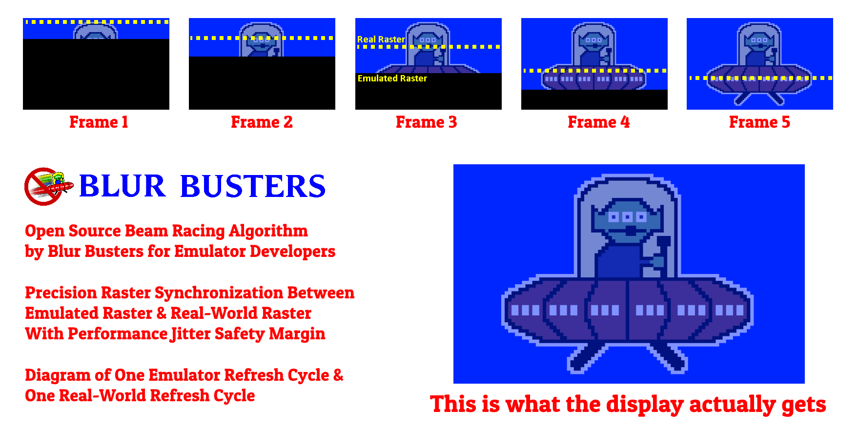
But did you know, the CRT beam simualtor is also real-time beam raceable too?

I helped WinUAE implement lagless VSYNC for latency of less than one refresh cycle, using the VSYNC OFF frameslice beamracing technique.

The CRT beam simulator can be combined with this algorithm (as long as the tearline is below the visible 'emulated' beam).

Basically, using VSYNC OFF to produce a lagless VSYNC ON by beamracing tearlines ahead of raster.

EmulatorRasterFollowerAlgorithm.png

At least three emulators use this algorithm: Toni's WinUAE, Tom's CLK, and an experimental fork of Calamity's GroovyMAME.

For my research of raster-precise steered tearlines, see Tearline Jedi on pouet.net.

I also open-sourced my cross platform raster calculator under the Apache license: RefreshRateCalculator.js
You can get a raster approximation simply as a time offset between VSYNC's, and this calculator can accept a noisy heartbeat, to compute a raster scan line number accurate to roughly 10-100us -- completely in Javascript, C#, or other high level language. Through this power, you can use this with microsecond busywaits (RTDSC etc) to steer tearlines. VSYNC OFF tearlines are just rasters, no matter the platform.

BTW, if you have a NVIDIA GPU and Windows, check my Javascript-based Kefrens Bars implementaton (yes, true beam racing in javascript, requires chome.exe --disable-gpu-vsync), https://testufo.com/raster51 .... Does not work in other browsers alas, only works with VSYNC OFF, and you need to compute your refresh rate (run at a lower Hz when doing this demo).

As you can see, Radeon/Geforce/Intel GPUs are still beamraceable today, even in high level language. Here's a YouTube video example of one of my early modern beam racing experiments, running in garbage-collected C# programming language, of all things. It's less than a millisecond between Present() and the pixel outputting at the raster in the GPU, as it's zero-lag for first pixel row of graphics underneath a tearline. Even DisplayPort and HDMI still outputs top-to-bottom, left-to-right, serialized. Video raster topology is still the same from 1920s to 2020s, even in a 240Hz VRR signal.

Founder of www.blurbusters.com and www.testufo.com
- Research Portal
- Beam Racing Modern GPUs
- Lagless VSYNC for Emulators

Reply 177 of 177, by Trypticon

User metadata
Rank Newbie
Rank
Newbie
Mr_Blastman wrote on 2024-07-11, 17:00:
Trypticon wrote on 2024-05-26, 14:08:

With a high pitch CRT, the scanlines seem less prominent, but that's not the only factor. E.g. before I did a focus adjustment on the used Eizo Multisync (0.28 mm pitch) I acquired sometime ago, there were large areas in the middle of the screen that seemed scanline free 😉

The only CRTs I recall seeing actual scanlines on were the early 80s IBM Color Monitors, and later 90s era Super VGA monitors when running in lower resolutions such as 640x480. My Viewsonic G771(I think) aperture grille display did this, and was quite a nice monitor for the period.

What I mean by scanlines in this context is also visible on your CM-5 shader. You can still see a difference on these high pitch slot displays when it comes to "scanlined" and "scanline free". Check out this pic from one of my Tvs, compare e.g. the blue top area vs. the green.

r34kon7n.jpg

On my multisync monitor, running in comparable low resolution gives way more obvious lines (not necessarly attractive depending on the content). With 640x480, the gaps shrink, but it's still different from 800x600 "mask only".

zuvuxce7.jpg