VOGONS


Project: Full Can Clock Oscillator Replacement

Topic actions

Reply 60 of 124, by feipoa

User metadata
Rank l33t++
Rank
l33t++

Thank you. I will look into your suggestions once I can confirm that I can at least programme the ATtiny85 successfully with my Arduino. If I cannot programme the ATtiny85, I probably cannot programme the ATtiny13. At this point, it doesn't matter to me how bloated or slim the code is as long as it fits in the AVR and is functional.

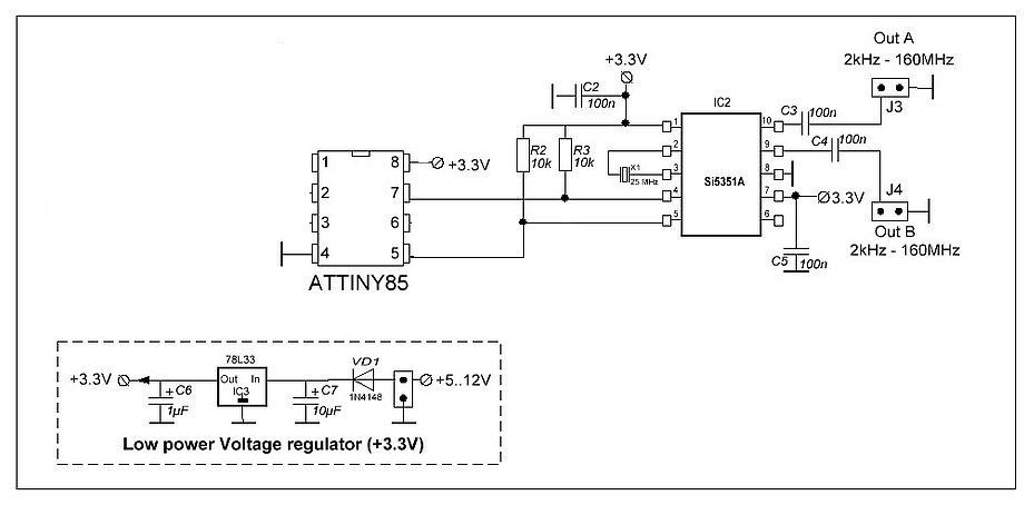
Since I already know the Adafruit SI5351 code works, I am starting with that code on the ATtiny85. I connected it per the youtube example I posted earlier. I followed the *blink* example in the following testbed:

The attachment Arduino_ISP_mode_for_ATtiny85.JPG is no longer available

Although it appears like the *blink* code is working on the ATtiny85, I do receive these mismatch errors in the IDE after uploading:

avrdude: verification error, first mismatch at byte 0x001f
0x20 != 0x24
avrdude: verification error; content mismatch
The attachment Programme_Blink_code_to_ATtiny85_error.png is no longer available

I'm not sure if I need to worry about this error. In the screenshot, you can see I selected the clock of 4 MHz (internal). If I select any other values, the 500 ms delay in the code is way off from reality. With a stopwatch, I measured about 9 seconds for 10 blinks; it should be 10 seconds. I don't understand how we are supposed to know what the correct frequency is, but the Youtuber says if you "burn bootloader", this won't matter. He did not explain further.

The problem comes when I want to programme the ATtiny85 again. I get an error stating I have selected the wrong microcontroller and I can use -F to bypass this restriction. Reading up on -F, it seems like this is something we generally do not want to do because it doesn't help in 99% of the cases, and may ruin the microcontroller. The only way I have figured out how to re-programme the ATtiny85 again is to play around with the reset button on the Arduino and in some unrepeatable sequence, remove power to the ATtiny85. If I can manage to hit the "compile/send code" button in the Arduino IDE while doing some sequence of Arduino resets and removing/reapplying power to the ATtiny85, I can re-programme the ATtiny85. However, I will still receive the above mismatch error at byte 0x001f.

The menus in the Youtube example were a little different in my version of the IDE, which is 1.8.19. For example, on that user, he was able to select ATtiny 25/45/85, whereas my options were ATtiny 25/45/85 (No bootloader), ATtiny 25/45/85 (Optiboot), ATtiny 25/45/85 (Micronucleus/Digispark). I'm not sure what those later two are, but must have something to do with burning a bootloader. I selected the No bootloader option.

Having to perform this mickey mouse juggling act to re-programme ATtiny85 whenever we want to change the frequency on the SI5351 isn't very practical. Nonetheless, moving on...

I then did my juggling act to programme the ATtiny85 with the stock Adafruit SI5351 code (with Serial Monitor commented out). The ATtiny85 did programme, but I received a similar mismatch error:

The attachment Programme_Adafruit_SI5351_code_to_ATtiny85_error.png is no longer available
avrdude: verification error, first mismatch at byte 0x000b
0xc0 != 0xc2
avrdude: verification error; content mismatch

Curiously, the upload screen says the sketch is only using 157 bytes of SRAM, but when I uploaded it to the Arduino EtherTen, the same sketch was using 436 bytes. Is the compiler removing some code when it detects at ATtiny85?

Tomorrow, I will manually wire this ATtiny85 to the Wiretap PCB to see if the frequency is set to 84.4 MHz. Somewhere online I saw that the I2C pins on the ATtiny85 were: pin 7 is SDA and pin 6 is SCL, however I'm not sure if I need to set this up in code?

EDIT: By the way, the ATtiny13 is 1.3 mm smaller than the ATtiny85, so I will return to it if I can get the ATtiny85 working.

Plan your life wisely, you'll be dead before you know it.

Reply 61 of 124, by rasz_pl

User metadata
Rank l33t
Rank
l33t
feipoa wrote on 2024-10-09, 11:47:

avrdude: verification error, first mismatch at byte 0x001f 0x20 != 0x24

wires too long, noisy power? Maybe lowering SPI_CLOCK in ArduinoISP sketch can fix this?

feipoa wrote on 2024-10-09, 11:47:

Curiously, the upload screen says the sketch is only using 157 bytes of SRAM, but when I uploaded it to the Arduino EtherTen, the same sketch was using 436 bytes. Is the compiler removing some code when it detects at ATtiny85?

Afaik when you select Board in Arduino IDE you swap some underlying board library. Smaller micro has less resources (tiny has only 5-6 gpio pins for example) means uses less resources to init.

feipoa wrote on 2024-10-09, 11:47:

EDIT: By the way, the ATtiny13 is 1.3 mm smaller than the ATtiny85, so I will return to it if I can get the ATtiny85 working.

meh, ATtiny85 is perfectly fine, especially considering you got plenty spare.

https://github.com/raszpl/FIC-486-GAC-2-Cache-Module for AT&T Globalyst
https://github.com/raszpl/386RC-16 memory board
https://github.com/raszpl/440BX Reference Design adapted to Kicad
https://github.com/raszpl/Zenith_ZBIOS MFM-300 Monitor

Reply 62 of 124, by feipoa

User metadata
Rank l33t++
Rank
l33t++

I think I figured out the issue with the problematic writing to the ATtiny85 - USB 3 power was insufficient and/or the Arduino's VRM is faulty.

I connected an external wall art power supply first, but the 5 V VRM on the Arduino was overheating, approaching 82 C, and the VRM's voltage output dropped to 4 V. The Arduino's 5V output couldn't seem to power the ATtiny85 (using blink test to confirm). The VRM, which is a MC33269DTRK-5.0G, may be turning bad. Not wanting to troubleshoot this now, I decided to use the Vin input on the Arduino, and ran Arduino power (Vin) using a desktop variable supply. The issue with code mismatch disappeared. I programmed the Adafruit SI5351 code to the ATtiny85 without issue.

Next, I jumpered the ATtiny85 to the Wiretap SI5351 PCB, using pin7 as SDA and pin6 as SCL. Connected the scope, and nothing. Bugger.

The attachment ATtiny85_connected_to_Wiretap_SI5351_PCB.JPG is no longer available

Per my previous speculation, I think I need to configure the ATtiny85 to use I2C. Some tutorial here: https://www.gadgetronicx.com/attiny85-i2c-protocol-tutorial/ This is approaching the limit of how much time I want to invest... will give this another night or two.

Plan your life wisely, you'll be dead before you know it.

Reply 63 of 124, by rasz_pl

User metadata
Rank l33t
Rank
l33t
feipoa wrote on 2024-10-10, 03:47:

I jumpered the ATtiny85 to the Wiretap SI5351 PCB, using pin7 as SDA and pin6 as SCL.

why? cant just wire random pins 😮

feipoa wrote on 2024-10-10, 03:47:

Per my previous speculation, I think I need to configure the ATtiny85 to use I2C.

Wire appropriate pins, hardware I2C is at SDA pin 5, SCL pin 7.
This https://zl2pd.com/sugarcube_VFO.html also uses hardware I2C:
SugarCube_VFO_Schematic.gif

tiny5351 bitbangs i2c manually, probably for smaller code, uses SCL pin 6, SDA pin 7

https://github.com/raszpl/FIC-486-GAC-2-Cache-Module for AT&T Globalyst
https://github.com/raszpl/386RC-16 memory board
https://github.com/raszpl/440BX Reference Design adapted to Kicad
https://github.com/raszpl/Zenith_ZBIOS MFM-300 Monitor

Reply 64 of 124, by feipoa

User metadata
Rank l33t++
Rank
l33t++

I haven't had time to look through the links yet. Do I only need to swap my SDA and SCL pins? And add two 10K pull-ups to 5V ? What about adding code to make the ATtiny85's universal serial interface (USI) operate in I2C mode? https://www.gadgetronicx.com/attiny85-i2c-protocol-tutorial/ Or does the bulky Adafruit SI5351 code take care of that when it compiles for the ATtiny85? Thanks.

Plan your life wisely, you'll be dead before you know it.

Reply 65 of 124, by rasz_pl

User metadata
Rank l33t
Rank
l33t
feipoa wrote on 2024-10-10, 06:03:

I haven't had time to look through the links yet. Do I only need to swap my SDA and SCL pins? And add two 10K pull-ups to 5V ?

yep, like https://www.f4htb.fr/2018/10/09/attiny85-si53 … ia-ide-arduino/ Attiny85_SI5351-1.png

feipoa wrote on 2024-10-10, 06:03:

What about adding code to make the ATtiny85's universal serial interface (USI) operate in I2C mode? https://www.gadgetronicx.com/attiny85-i2c-protocol-tutorial/ Or does the bulky Adafruit SI5351 code take care of that when it compiles for the ATtiny85? Thanks.

adafruit library should do everything in the background

What sketch are you flashing?

https://github.com/raszpl/FIC-486-GAC-2-Cache-Module for AT&T Globalyst
https://github.com/raszpl/386RC-16 memory board
https://github.com/raszpl/440BX Reference Design adapted to Kicad
https://github.com/raszpl/Zenith_ZBIOS MFM-300 Monitor

Reply 66 of 124, by feipoa

User metadata
Rank l33t++
Rank
l33t++

I'm using the Adafruit SI5351 sketch that downloads with the Arduino IDE 1.8.19 for Linux. I don't recall if I had to request the IDE to download the Adafruit sketch + library, or if it was already there and I clicked "include library". Nonetheless, I've attached the two libraries w/example that I'm using. I'm using the included example sketch from the SI5351 library, but only using PLL_A. I've also commented out the Serial.Monitor code.

I think those two 10K pull-ups are already on the Wiretap PCB. Thus, I will try swapping the SDA and SCL pins and running the ATtiny85 at 3.3 V (instead of 5 V)...

The attachment Adafruit_Si5351_and_BusIO_Library.zip is no longer available

Plan your life wisely, you'll be dead before you know it.

Reply 67 of 124, by rasz_pl

User metadata
Rank l33t
Rank
l33t
feipoa wrote on 2024-10-10, 07:10:

and running the ATtiny85 at 3.3 V (instead of 5 V)

makes no difference, I2c is open drain aka only pulls to ground meaning no 5V signals go from arduino to PLL chip

You can also try

#include "tiny5351.h"

void setup() {
si5351_freq(33000000, 0);
}
void loop() {}

with rewired SCL pin 6, SDA pin 7

https://github.com/raszpl/FIC-486-GAC-2-Cache-Module for AT&T Globalyst
https://github.com/raszpl/386RC-16 memory board
https://github.com/raszpl/440BX Reference Design adapted to Kicad
https://github.com/raszpl/Zenith_ZBIOS MFM-300 Monitor

Reply 68 of 124, by feipoa

User metadata
Rank l33t++
Rank
l33t++

Thanks for your help. Looks like the only issue was that I was using the riyas configuration for the SDA/SCL pins, whereas Adafruit had a different assignment. I was able to get the Adafruit code working well with the ATtiny85. I tested integer and fractional modes. I also tested the riyas example, as well as the 6-line code you provided for use with the riyas tiny5351 library. I programmed the ATtiny85 a dozen or so times to compare the Adafruit and riyas libraries. All tests of the riyas code were noticeably jittery, whereas the Adafruit code was not. I didn't detect much difference in jitter between the Adafruit integer (PLLA) and fractional (PLLB) outputs, but perhaps integer was marginally better. I didn't analyse this in depth.

At some point, I noticed my variable DC supply clipping at the user set current limits, which was ~450 mA. I pulled the jumper cables out, but it was too late. Something on the Wiretap PCB died. Quick measurements reveal that there's no voltage output from the 3.3V VRM. I may have to pull this IC from my spare aliexpress SI5351 board.

At this point, does anyone want to modify wiretap's PCB to make room for an ATtiny85 8-SOIC? Rather than the existing breakout header, we'd want to breakout ATtiny85 pins 1, 5, 6, and 7 in order to use ISP to programme it.

Plan your life wisely, you'll be dead before you know it.

Reply 69 of 124, by rasz_pl

User metadata
Rank l33t
Rank
l33t
feipoa wrote on 2024-10-10, 13:40:

All tests of the riyas code were noticeably jittery, whereas the Adafruit code was not. I didn't detect much difference in jitter between the Adafruit integer (PLLA) and fractional (PLLB) outputs, but perhaps integer was marginally better. I didn't analyse this in depth.

Computers DGAF, in fact faster computers clockgens intentionally inject jitter (Spread Spectrum) to minimize RFI emissions.
There is a ton of tuning knobs on SI5351 like output drive strength for example, to get them all just right one needs https://www.skyworksinc.com/Application-Pages … er-Pro-Software

feipoa wrote on 2024-10-10, 13:40:

At some point, I noticed my variable DC supply clipping at the user set current limits, which was ~450 mA. I pulled the jumper cables out, but it was too late. Something on the Wiretap PCB died. Quick measurements reveal that there's no voltage output from the 3.3V VRM.

You had motherboard with SI5351 board soldered, plugged PSU, connected to arduino plugged into another PC and powered by another separate PSU? Were all power supplies plugged into same circuit? Might be some ungrounded floating supply shenanigans. In general I would try to power everything from one supply, either PC or lab, and unplug from motherboard when programming.

feipoa wrote on 2024-10-10, 13:40:

At this point, does anyone want to modify wiretap's PCB to make room for an ATtiny85 8-SOIC? Rather than the existing breakout header, we'd want to breakout ATtiny85 pins 1, 5, 6, and 7 in order to use ISP to programme it.

whats wrong with hot glue stick gluing it on its back to the SI5351 board? 😀

Now that you have basics working add ADC readout and potentiometer for smooth frequency control, then small LCD and you have perfect standalone solution.

https://github.com/raszpl/FIC-486-GAC-2-Cache-Module for AT&T Globalyst
https://github.com/raszpl/386RC-16 memory board
https://github.com/raszpl/440BX Reference Design adapted to Kicad
https://github.com/raszpl/Zenith_ZBIOS MFM-300 Monitor

Reply 70 of 124, by feipoa

User metadata
Rank l33t++
Rank
l33t++

At the instant of the current clipping, the only power supply being used was my variable supply at 5 V (no motherboard, no Arduino, no USB, no wall wart, no AT PSU). I think some alligator clips must have shorted somewhere. I should have placed the Wiretap PCB on the breadboard, but I didn't, and it was a rats nest.

For the time being, I do plan on piggy packing the ATtiny85 to the existing PCB. The tricky part will be to pull out ATtiny85 pins 1, 5, 6, 7 to a header without a redesign. I'll have to wire in a loose header cable. Alternately, I think I can epoxy a 4-pin header to the side of the PCB. I need to assemble another unit first.

Plan your life wisely, you'll be dead before you know it.

Reply 71 of 124, by feipoa

User metadata
Rank l33t++
Rank
l33t++

Here's my prototype of the Wiretap full can oscillator replacement with at ATtiny85. I think the tiny85 should be able to fit on the PCB with a redesign. The original header (5V, GND, SCL, SDA) was replaced with RESET', MOSI, MISO, SCK to use with Arduino ISP.

The attachment Wiretap_variable_oscillator_with_ATtiny85_1.JPG is no longer available
The attachment Wiretap_variable_oscillator_with_ATtiny85_2.JPG is no longer available
The attachment Wiretap_variable_oscillator_with_ATtiny85_3.JPG is no longer available

Plan your life wisely, you'll be dead before you know it.

Reply 72 of 124, by rasz_pl

User metadata
Rank l33t
Rank
l33t
feipoa wrote on 2024-10-11, 12:38:

replaced with RESET', MOSI, MISO, SCK to use with Arduino ISP.

How does that work with no ground? unplug and use one of DIP pins?
Add another header for pins 3 and 4 for potentiometer and you wont have to constantly reprogram it.

https://github.com/raszpl/FIC-486-GAC-2-Cache-Module for AT&T Globalyst
https://github.com/raszpl/386RC-16 memory board
https://github.com/raszpl/440BX Reference Design adapted to Kicad
https://github.com/raszpl/Zenith_ZBIOS MFM-300 Monitor

Reply 73 of 124, by feipoa

User metadata
Rank l33t++
Rank
l33t++

I don't understand the question. 5V and GND on the original header weren't needed for anything, since 5V and GND come from the motherboard (machine pins). If you are referring to GND on the ATtiny85, it is connected.

Most likely, I will assemble 5 or 6 units and just have them set to the frequency I want them to run at, so no need to keep reprogramming. Alternately, I've also assembled another replacement clock unit which just uses a PLL and a jumper block to switch frequencies. It has the same footprint as the wiretap PCB. I'll report on that later.

Plan your life wisely, you'll be dead before you know it.

Reply 74 of 124, by feipoa

User metadata
Rank l33t++
Rank
l33t++

I tested the unit in motherboard today, at 85.00 MHz. No issue.

I pulled the unit out of the motherboard, placed it in a breadboard, and tried to re-programme it, but it wouldn't programme. I received this error:

avrdude: Yikes!  Invalid device signature.
Double check connections and try again, or use -F to override
this check.

An error occurred while uploading the sketch

The Arduino ISP IDE isn't finding the ATtiny85. Looking at my wiring, I realise that I2C and ISP are using some of the same pins.

I2C is used by the ATtiny85 to programme the SI5351 and on the Adafruit code, it is using these pins on the ATtiny85:

pin 5 for SDA
pin 7 for SCL

ISP is used by the Arduino IDE to send new code to the ATtiny85. ISP is using these pins on the ATtiny85:

pin 1 for RESET'
pin 5 for MOSI
pin 6 for MISO
pin 7 for SCK

Thus, I am supposing that the Arduino IDE cannot write to the ATtiny85 because the ATtiny85 has two of the desired pins in use. Is there an easy way to move I2C SDA to pin 2 and SCL to pin 3? If not, I was thinking to jumperise pins 5 & 7 for programming purposes.

Wanting to test my theory, I disconnected the ATtiny85's I2C pins 5 & 7 from the SI5351, but left pins 5 & 7 connected for ISP communication with the Arduino IDE. Unfortunately, I received the same error in the IDE.

I'm not sure what I'm doing wrong. The only difference between my breadboard setup to programme the ATtiny85 is that on the breadboard, the ATtiny85 was powered by 5.0 V, while on the Wiretap PCB, it is powered by that small 3.3 V regulator.

EDIT: I can confirm that the ATtiny85 needs 5 V power in order to programme it with the Arduino ISP IDE. Rewiring this now. The issue with doubling up pins 5 & 7 is still unresolved.

Plan your life wisely, you'll be dead before you know it.

Reply 75 of 124, by rasz_pl

User metadata
Rank l33t
Rank
l33t
feipoa wrote on 2024-10-12, 09:54:

The Arduino ISP IDE isn't finding the ATtiny85. Looking at my wiring, I realise that I2C and ISP are using some of the same pins.

SPI is push-pull. In theory it could work fine with pull-up resistors, maybe the ones on your pcb are too strong.

feipoa wrote on 2024-10-12, 09:54:

Is there an easy way to move I2C SDA to pin 2 and SCL to pin 3?

yes, using tiny5351 with bitbanged I2c. Modify i2cmaster.S

#define SDA_PORT        PORTB           // SDA Port D
#define SDA 2 // SDA Port D, Pin 2

#define SCL_PORT PORTB // SCL Port B
#define SCL 1

to
#define SDA 3
#define SCL 4

feipoa wrote on 2024-10-12, 09:54:

If not, I was thinking to jumperise pins 5 & 7 for programming purposes.

also good

feipoa wrote on 2024-10-12, 09:54:

Wanting to test my theory, I disconnected the ATtiny85's I2C pins 5 & 7 from the SI5351, but left pins 5 & 7 connected for ISP communication with the Arduino IDE. Unfortunately, I received the same error in the IDE.

disconnected before or after pullup resistors?

feipoa wrote on 2024-10-12, 01:58:

5V and GND on the original header weren't needed for anything

followed by

feipoa wrote on 2024-10-12, 09:54:

EDIT: I can confirm that the ATtiny85 needs 5 V power in order to programme

😀 As I said you dont need to worry about powering tiny from 3.3V - "I2c is open drain aka only pulls to ground meaning no 5V signals go from arduino to PLL chip". You can wire it to 5V on the pcb. 5V and GND on the original header were there so you wouldnt have to constantly arrange a proto board every time you program it, just plug one cable and go.

https://github.com/raszpl/FIC-486-GAC-2-Cache-Module for AT&T Globalyst
https://github.com/raszpl/386RC-16 memory board
https://github.com/raszpl/440BX Reference Design adapted to Kicad
https://github.com/raszpl/Zenith_ZBIOS MFM-300 Monitor

Reply 76 of 124, by feipoa

User metadata
Rank l33t++
Rank
l33t++

Thanks for your detailed replies.

I'm not using tiny5351 code because the jitter was off the chart. However, there's no longer any immediate need to worry about ISP and I2C sharing pins; apparently they can coexist. The whole issue I was having with programming was entirely related to powering ATtiny85 with 3.3 V.

On the other hand, if someone knows how to redirect the I2C pins with the Adafruit code, I'll probably adjust the assignments anyway. I took a brief look through the code and libraries, but nothing jumped out at me.

OK, I understand why the 5V header was on the original design; it was for a specific case whereby a user would want to leave the clock chip in the motherboard with the motherboard turn off, then programme it. But couldn't the clock chip be programmed with the motherboard powered up and sitting at the DOS prompt?

EDIT:
but with the original design, an Arduino always had to be connected to the clock chip, just to turn the clock on. Thus, the motherboard would need to be energised to programme the SI5351.

Plan your life wisely, you'll be dead before you know it.

Reply 77 of 124, by rasz_pl

User metadata
Rank l33t
Rank
l33t
feipoa wrote on 2024-10-12, 11:06:

I'm not using tiny5351 code because the jitter was off the chart.

You can disable Spread Spectrum https://www.reddit.com/r/amateurradio/comment … lp_with_si5351/
like Adafruit code does

/* Disable spread spectrum output. */
enableSpreadSpectrum(false);

edit tiny5351.c adding this:

uint8_t i2cRead(uint8_t reg)
{
uint8_t ret;

i2c_start_wait(I2C_WRITE);
i2c_write(reg);
i2c_rep_start(I2C_READ);
ret = i2c_readNak();
i2c_stop();
return ret;
}

uint8_t enableSpreadSpectrum(_Bool enabled)
{
uint8_t regval;
regval = i2cRead(149);
if (enabled) {
regval |= 0x80;
} else {
regval &= ~0x80;
}
i2cSendRegister(149, regval);
return 0;
}

just under "#define I2C_READ 0b11000001" line, and modify this:

i2c_init();
setupPLL(SI_SYNTH_PLL_A, 30, 0, 1,R_DIV_NA);

to read:

i2c_init();
enableSpreadSpectrum(false);
setupPLL(SI_SYNTH_PLL_A, 30, 0, 1,R_DIV_NA);
feipoa wrote on 2024-10-12, 11:06:

However, there's no longer any immediate need to worry about ISP and I2C sharing pins; apparently they can coexist. The whole issue I was having with programming was entirely related to powering ATtiny85 with 3.3 V.

so 10Kohm pullups dont interfere with PSI after all, great

feipoa wrote on 2024-10-12, 11:06:

OK, I understand why the 5V header was on the original design; it was for a specific case whereby a user would want to leave the clock chip in the motherboard with the motherboard turn off, then programme it. But couldn't the clock chip be programmed with the motherboard powered up and sitting at the DOS prompt?

no and no
- VIN on the header is connected to motherboard 5V, connecting programmer to this pin would make whole motherboard try to power ON from your arduino/programmer 😁
- powering device from one PSU while powering programmer from another isolated/floating ground PSU is a bad idea, you never know where the ground is going to be. Plenty of people experience being lightly zapped by their laptop while touching stationary PC case or trying to plug monitor for example https://www.makeuseof.com/avoid-laptop-electric-shocks/

Imo the idea was you power external Arduino from the 5V on Wiretaps PCB programmer header.
Safest is to unplug Wiretaps PCB from Motherboard, plug programmer, program attiny, plug back to motherboard.

https://github.com/raszpl/FIC-486-GAC-2-Cache-Module for AT&T Globalyst
https://github.com/raszpl/386RC-16 memory board
https://github.com/raszpl/440BX Reference Design adapted to Kicad
https://github.com/raszpl/Zenith_ZBIOS MFM-300 Monitor

Reply 78 of 124, by feipoa

User metadata
Rank l33t++
Rank
l33t++
rasz_pl wrote on 2024-10-12, 13:38:

- VIN on the header is connected to motherboard 5V, connecting programmer to this pin would make whole motherboard try to power ON from your arduino/programmer :D

lol, yeah, I realised this condition when I woke up today. Then got to wondering again what the 5V header pin was for. I never used it on the original Wiretap PCB (no ATtiny85).

rasz_pl wrote on 2024-10-12, 13:38:

- powering device from one PSU while powering programmer from another isolated/floating ground PSU is a bad idea, you never know where the ground is going to be.

I've been jumpering the Arduino's ground to the variable power supply ground to avoid the floating ground. Is this not the correct approach? Unfortunately, whenever I try to remove the external PSU and usilise the Arduino's 5V regulator to power the clock gen PCB, I get programming errors. The Wiznet 5100 chip on my EtherTen gets hot (50 C) and I think it is limiting the 5V rail on my EtherTen, or my 5V VRM is failing. I've ordered a regular Uno w/out the ethernet to check this. I don't like the idea of having to use an external PSU for the clock gen PCB.

rasz_pl wrote on 2024-10-12, 13:38:

Imo the idea was you power external Arduino from the 5V on Wiretaps PCB programmer header.
Safest is to unplug Wiretaps PCB from Motherboard, plug programmer, program attiny, plug back to motherboard.

As I recall it, when I was testing the original wiretap design (no ATtiny85), I was doing so with the motherboard powered up to programme the SI5351 w/Arduino. I only had the SDA and SCL pins connected and the Arduino powered by USB only. Seemed to work fine, but I guess I should have also tied the MB and Arduino grounds together?

I can confirm, that with the ATtiny85 connected to the Arudino ISP, I cannot power on my motherboard (screen stays blank). I didn't try programming it in this state. Thus, you are probably right, I'll have to remove the PCB and programme it outside the motherboard. In this case, having a 5V/GND header will eliminate the need for a breadboard or other types of jumper clips.

Thanks for the code additions. I'll look into it with tiny5351.c If disabling spread spectrum on tiny5351 results in the same clock output as the Adafruit code, I'll switch to tiny5351.c. For the simple call you provided here,

#include "tiny5351.h"

void setup() {
si5351_freq(33000000, 0);
}
void loop() {}

Is tiny5351 _freq() using fractional mode (PLLA) ? Is there an equivalent integer mode (PLLB) available with tiny5351?

Plan your life wisely, you'll be dead before you know it.

Reply 79 of 124, by rasz_pl

User metadata
Rank l33t
Rank
l33t
feipoa wrote on 2024-10-12, 21:23:

whenever I try to remove the external PSU and usilise the Arduino's 5V regulator to power the clock gen PCB, I get programming errors.

put a scope on 5V to see whats going on, might be sagging from additional power demand. No idea what regulator EtherTen is using, bight be undersized

feipoa wrote on 2024-10-12, 21:23:

The Wiznet 5100 chip on my EtherTen gets hot (50 C) and I think it is limiting the 5V rail on my EtherTen,

https://forum.arduino.cc/t/ethernet-shield-ge … ly-hot/399836/3
W5100 takes 138-146mA, 183mA max. Up to 600mW turned to heat. Its a hungry hot boy.

feipoa wrote on 2024-10-12, 21:23:

As I recall it, when I was testing the original wiretap design (no ATtiny85), I was doing so with the motherboard powered up to programme the SI5351 w/Arduino. I only had the SDA and SCL pins connected and the Arduino powered by USB only. Seemed to work fine, but I guess I should have also tied the MB and Arduino grounds together?

Frankly I dont believe you ;] There is zero* chance of this working with no ground connection. I2C works by shorting to ground, no common ground connection means arduino wasnt shorting anything from 5351 perspective.

* some magical parasitic effect due to two SI5351 I/O pins at different potential? but even that wouldnt work in cases where both need to be grounded at same time.

feipoa wrote on 2024-10-12, 21:23:

Is tiny5351 _freq() using fractional mode (PLLA) ? Is there an equivalent integer mode (PLLB) available with tiny5351?

Thats not how it works, Adafruit is catering to noobs and oversimplifies things all the way to misleading 😐. Both PLLA and PLLB are fully independent and can work in both* modes ... except there is only ONE mode 😀 PLL Is always fractional, thats how they all work (a+b/c), but if you carefully select frequency you can make the fraction (b/c) read 0 (by using b=0, 0 divided by anything = 0). SI5351 has a magic register MS0_INT you can set to Force this by internally ignoring the b/c parameters but neither Adafruit_SI5351.cpp nor si5351.ino do this, setting it will simply result in wrong frequency output.

You got 25MHz crystal on your board. Means you can make "perfect" (as in least jitter) 75MHz with no fractions. 25 x 24 : 8 = 75
You cant make 76MHz without fractions, you need 25 x 24.32 : 8 = 76
but you can make "perfect" 78.125MHz because 25 x 25 : 8 = 78.125
next is 81.25 and so on.

But it doesnt matter, computers DGAF about jitter on FSB. Your smartphone has all its clocks generated by PLL in this fractional manner and is able to discriminate on signals send at 2.6GHz at more than 1 symbol per Hertz. Dont worry about it, everything nowadays uses PLLs and everything still works fine 😀

EDIT: I think those are the only possible integer "mode" outputs in 20-160 MHz range? :

20.3125
21.875
21.09375
22.65625
23.4375
24.21875
25
25.78125
26.5625
27.34375
28.125
37.5
39.0625
40.625
42.1875
43.75
45.3125
46.875
48.4375
50
51.5625
53.125
54.6875
56.25
75
78.125
81.25
84.375
87.5
90.625
93.75
96.875
100
103.125
106.25
109.375
112.5
150
156.25

generated with this javascript

for (let x = 15; x<=90; x++) { 
if ((25*x >=600) && (25*x <= 900)) {
for (const y of [1, 2, 4, 8, 16, 32, 64, 128]) {
if ((25*x/y > 20) && (25*x/y <= 160)) console.log(25*x/y)
}
}
}

https://github.com/raszpl/FIC-486-GAC-2-Cache-Module for AT&T Globalyst
https://github.com/raszpl/386RC-16 memory board
https://github.com/raszpl/440BX Reference Design adapted to Kicad
https://github.com/raszpl/Zenith_ZBIOS MFM-300 Monitor