VOGONS


The 286 Laptop Restoration Thread

Topic actions

Reply 80 of 138, by miclass

User metadata
Rank Newbie
Rank
Newbie

Ciao all - small update from here - I spent a lot of time testing continuity of all traces around the Boost 12V components, luckly everything seems fine for my tester (I admit I would have prefered finding something wrong...at least I would have found a problem...).

I had already dissoldered Q2, Q3, Q4, Q21, Q22, Q23 and checked them with the components tester and they also seem good. Same for L3 and diode 12. I decided to dissolder also UPA1600 and test each ones of its mosfet singularly,...they also seem all fine, both for the component tester and I also did a try generating a PWM at 70khz from arduino, it seemed to switch properly (I will try the same also with Q2, Q3 and Q4...).

I am quite clueless in this moment, I have ordered a new UPA1600 just because I have found it on aliex for few € and mine seems a little bit"baked" (it has lost the tag on it)...even if it seems working. When I will receive the UPA1600, I will try to reassemble all components and test again,...hopefully with my cheap oscilloscope I will get some hint before seeing again some white smoke... 😀 Hope to have some good news soon!

Here some pics from the board and some particular parts:
board-front.jpg
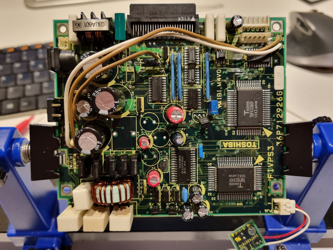
PSU upside, some components missing...I tried to clean it as much as possible with isopropilic alcool

board-back.jpg
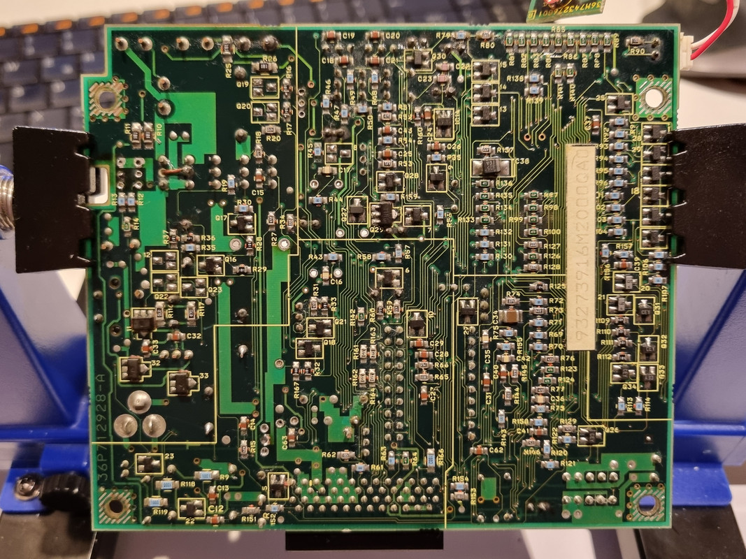
PSU backside...here I had to change Q29...

C4-mess-small.jpg
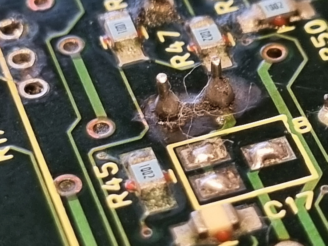
C4 after replacement...this was really a mess, C4 and C7 really leaked a lot and corrosion was important, remove them was a pain... The trace on the left seems damage but for the tester is Ok...

L3-problem-small.jpg
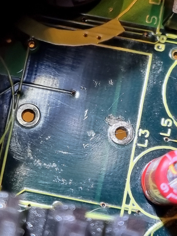
L3 place...here there is something strange on the right hole, I does measure as a short but it does not look so good...again there was some corrosion here...

UPA1600-backed-small.jpg
UPA1600 - it lost the tag on it while cleaning...I don't know if due to overheat or what...

Reply 81 of 138, by FuST

User metadata
Rank Newbie
Rank
Newbie

That looks like a lot of corrosion on the solder joints.
I'd say the uPA1600's are probably fine (they can take quite some abuse) and the problem is more likely to be a damaged trace somewhere.

First things first though: check if all totempole driver combinations see a PWM signal. You'll need to use single trigger mode on your 'scope for that.
Next check if all the switchmode converters actually switch. I.e. check the output voltages using a 'scope in single trigger mode.

That way you can isolate the problem to a single converter/rail and work from there.
It's all about confirming what does work, crossing it off (I literally cross it off in the schematic) and checking whatever is left in the end. Tedious but doable.

Blog | YouTube

Reply 82 of 138, by perezx

User metadata
Rank Newbie
Rank
Newbie

Hey guys, again!
I was missing for some time and the laptop got covered by dust. Finally my friend agreed to have a look at it and he found that Q29 was one of the problems - at 1V Drain-Source voltage it worked like everything okay, but at 2V Ids = 2A, so some kind of avalanche breakdown.
When Q29 was replaced, the PSU reached stable +18V on primary circuit.... but NO PWM on any other converter. It even does not try to start them up. WTH? Any Ideas?

Reply 83 of 138, by FuST

User metadata
Rank Newbie
Rank
Newbie
perezx wrote on 2024-05-29, 14:32:

When Q29 was replaced, the PSU reached stable +18V on primary circuit.... but NO PWM on any other converter. It even does not try to start them up. WTH? Any Ideas?

Are you saying the +18V internal rail comes up and stays up (I.e. the microprocessor keeps generating PWM for it indefinitely) while the other converters are completely dead?
That doesn't make any sense to me. If the microprocessor senses a fault it should shut down everything immediatly, including the +18V internal converter.

Blog | YouTube

Reply 84 of 138, by miclass

User metadata
Rank Newbie
Rank
Newbie
FuST wrote on 2024-05-22, 06:03:
That looks like a lot of corrosion on the solder joints. I'd say the uPA1600's are probably fine (they can take quite some abuse […]
Show full quote

That looks like a lot of corrosion on the solder joints.
I'd say the uPA1600's are probably fine (they can take quite some abuse) and the problem is more likely to be a damaged trace somewhere.

First things first though: check if all totempole driver combinations see a PWM signal. You'll need to use single trigger mode on your 'scope for that.
Next check if all the switchmode converters actually switch. I.e. check the output voltages using a 'scope in single trigger mode.

That way you can isolate the problem to a single converter/rail and work from there.
It's all about confirming what does work, crossing it off (I literally cross it off in the schematic) and checking whatever is left in the end. Tedious but doable.

I received the UPA1600 and I substituted it, even if as you are saying most probably it was working. Then I proceed to mount again all components I dissoldered in the meantime (Q19, Q20, Q22, Q23, Diode 8, Diode 12, Q2, Q3, Q4 and Q5)...all these componentes were fine according to my components testers. I checked again all connections to verify continuity and everything was good.

I connect the power supply with a bit of hope...but I got:

- immediately red led blinking, Q2 and Q3 very hot (there was some residual solder paste that smoked immediately)...I disconnected and then I tried to connect it again for very few seconds to just get some measure...but...
- Q2 and Q3 stooped to be hot (broken again?) and Q5 started to smoke...again I disconnected and connected again for very few seconds...something getting also a solid red led, sometimes also the led soldered on IC2 turned led without switching it on... then Q5 stopped to smoke, and Q2/Q3 started again....then...both seemed fine for few seconds (all led solid)...and
- Q14 created a lot of quite smoke...(I think it's broken now...)...and I disconnected everything...

Now I am very frustrated by this situation...I spent a lot of timing dissoldering/soldering again and testing components but I am not able to point out the problem, the board had a very erratic behaviour, seems different everytime I connect it to power, and I am really clueless in what to do next 🙁

i don't want to abandon this recovery project but it seems really an hard problem. Do you have any suggestion?

Thank you.
-miclass

Reply 85 of 138, by perezx

User metadata
Rank Newbie
Rank
Newbie
FuST wrote on 2024-06-07, 18:38:
perezx wrote on 2024-05-29, 14:32:

When Q29 was replaced, the PSU reached stable +18V on primary circuit.... but NO PWM on any other converter. It even does not try to start them up. WTH? Any Ideas?

Are you saying the +18V internal rail comes up and stays up (I.e. the microprocessor keeps generating PWM for it indefinitely) while the other converters are completely dead?
That doesn't make any sense to me. If the microprocessor senses a fault it should shut down everything immediatly, including the +18V internal converter.

Hi again, nice to meet you 😀
Sure, +18 rail shuts down soon (possibly when its time to power up other rails). I do not see what kind of error IC13 finds assuming that +18 is okay now and no other converter starts...

Reply 86 of 138, by miclass

User metadata
Rank Newbie
Rank
Newbie

Another update on my PSU, after the dramatic failure of some days ago I dissoldered some of the components that I saw smoking or becoming very hot, and I found:

Q14 to be broken apart, cracked between source/drain
Q29 KO
Q2 / Q3 still OK, according to my components tester
Q5 KO
Q6 KO

Then:
- what could cause such a catastrofic failure with components failing one after the other? I am doing a lot of testing on continuity to find out broken traces or shorts but no luck so far...
- how to proceed now? I have order spare parts to substitute these components but I think that if I reassemble everything and switch it on I will get the same result... could be an idea to proceed with an order and add one mosfet per time and check, avoiding to fry again everything?

Thanks!
-miclass

Reply 87 of 138, by FuST

User metadata
Rank Newbie
Rank
Newbie
perezx wrote on 2024-06-10, 08:30:

Sure, +18 rail shuts down soon (possibly when its time to power up other rails). I do not see what kind of error IC13 finds assuming that +18 is okay now and no other converter starts...

That is in line with what I would expect.
First things first: make sure you're waiting about 10-20 seconds in between tries when powering up the board as IC13 needs to be powered down completely for a second or two to fully reset it.
Next check the PWM in- and outputs of the UPA1600 buffers (IC5 & IC11). There should be a PWM signal there, even for a short while. Make sure you're using an oscilloscope capable of such short pulses and use single-shot mode to try to capture it.

miclass wrote on 2024-06-12, 12:30:

- what could cause such a catastrofic failure with components failing one after the other? I am doing a lot of testing on continuity to find out broken traces or shorts but no luck so far...
- how to proceed now? I have order spare parts to substitute these components but I think that if I reassemble everything and switch it on I will get the same result... could be an idea to proceed with an order and add one mosfet per time and check, avoiding to fry again everything?

There must be a short somewhere but it might be caused by something that's not so obvious.
In any case: stop applying power to the board when components get hot or start to smoke, the chances of causing a lot more damage that way are very high.
One thing that immediately springs to mind when reading the list of destroyed components is that the MOSFETs are constantly conducting, be it partially or completely *.

I'd check that the resistors responsible for pulling up the totem-pole drivers are within spec and are connected to the appropriate rails (+18V and V+ main, depending on the rail IIRC). Next check that the totem-pole transistors are good.
After that I'd backtrack the PWM signals like I described above in my reply to perezx.

EDIT: Forgot to add that you might be able to populate just one MOSFET at the time to test things out one at the time. Don't just take my word for it though, check the schematic and maybe simulate parts if you're unsure. Removing the wrong components (ex: pull-up resistors) can result in something just shorting to ground and frying things more.
They might pop again because the problem lies elsewhere (like the driving circuitry for example) which is one of the reasons I always advise to buy one or two more than you need.
And lastly: don't just throw parts at a problem without verifying it actually is problematic. That is a very expensive and frustrating way to troubleshoot things.

*: MOSFETs need to be driven to fully open/closed very fast, they have high resistance causing heating in the in-between region

Blog | YouTube

Reply 88 of 138, by Ilcecco

User metadata
Rank Newbie
Rank
Newbie

Hello All !

i'm currently trying to restore a couple of T1600. On the first one i think i cleaned and restored all the parts with the exception of the famous power board . I have a FIVPS4 and as first thing i recapped it all and cleaned all the leakage of the capacitors that were really in bad shape. I tried then to follow the troubleshooting guide and i found no problems until step 4 having no 18v on C6. I then replaced Q29 but still no luck. I also tried to replace IC11 but i now thing it was just a bad call during testing that lead me to think a signal was stopping there preventing VINT_EN to work. no changes after the replacement.

So far i had zero success in trying to follow step 4a, i use a Rigol DS1202 and i double checked the settings but it looks like i'm unable to trigger a signal whatsoever i do. I'm not 100% sure of my settings (with this board i'm not even sure of anything at this point 🙁

When the board is powered us my bench power supply stays at 12v with just 0.1A consumption that jumps for a couple of seconds to 0.11 if i try to push the button.

Trying with the multimeter i got few volts but not 12 testing for example Q4.

I checked the diodes and found no problems, with the exception that i can't find 3 and 2, unfortunately my silkscreen is not very good after all the cleaning.

I spent many evenings trying to track down the issue but i'm stuck and looking for advice. My skills are very far from yours and Fust ones especially.

Can you please help or give me any hints?

Thanks a lot!
Stefano

Reply 89 of 138, by FuST

User metadata
Rank Newbie
Rank
Newbie

@Ilcecco:
You're not getting any activity on VINT_EN? That would prevent everything else from working and explains the lack of PWM signals on the other drivers.
The 18V_INT converter powers on first, the other converters are started only once that is stable.
Are you getting anything on the VINT_EN_DRV signal? Test on both IC5 pin 2 and IC13 pin 10 to eliminate trace damage.
The signal is pulled to ground by R142, IC13 has to pull it up so make sure that it is receiving power and has a clock signal on pin 27.

Blog | YouTube

Reply 90 of 138, by Ilcecco

User metadata
Rank Newbie
Rank
Newbie

@fust:
Correct, no activity on VINT_EN. Perfect continuity between Ic5 and Ic13 pin10.

While investigating it i found maybe a culprit in Q30 that is not giving correctly 5v on emitter (less than 1v) so IC13 is not really fired up.

Waiting for some 2SA1313 to replace it and move forward.

Thanks!

Reply 91 of 138, by Ilcecco

User metadata
Rank Newbie
Rank
Newbie

@fust

A minor progress...

After Q30 replacement now ic2 is working properly and giving stabile 5v.

My problem is now that Q14 is not turning on, i replaced it and despite receiving 12.05v on source and 11.7v on gate doesn't output anything on drain.

Q12 and Q13 have similar readings on S and G but giving about 12v on D.

Found also Q5 quite hot and not giving anything on output (gate and source present). Replaced and now is cold but still not turning on.

Q29 is of course not powered given Q14 is not turning on...

Stuck again 😞

Thanks

Reply 92 of 138, by FuST

User metadata
Rank Newbie
Rank
Newbie

Well, ofcourse Q14 isn't turning on with 12V at the gate. It's a P-Channel MOSFET so it's gate should be pulled down to ground to turn it on.
Try to understand how the components and the parts of the circuit work, use a simulator to visualise parts if it helps (be aware that simulators don't tell the whole story, though!). Falstad's circuit simulator is easy to use: https://www.falstad.com/circuit/

Since Q14 is the switch providing 12V to the main DC-DC converter which generates the internal 18V rail nothing else is switching on.
Check the connection for VINT_EN (Q14 gate) to IC5 and check the input/output for that signal on IC5 looks correct.
Note that the uPA1600 is an open-collector type MOSFET array, it can only sink current (pull signal to ground) not source current (pull up to a certain voltage).

IC7 or IC8 could be bad as well providing the MPU with incorrect readings. Those aren't easy to test properly but fortunately they're relatively cheap.

Blog | YouTube

Reply 93 of 138, by Ilcecco

User metadata
Rank Newbie
Rank
Newbie

Hello Fust, many thanks for your help. Unfortunately my skills are limited so forgive my eventual stupid questions... I'll try the tool you suggested to better understand how things are working in this board. Is the a way to load/import your diagram to the tool ?

Currently i'm experiencing a regression once again : q30 seems unable to provide 5v to IC2 so IC13 is not powered and everything else is prevented to work.

From your diagram I didn't understand how Q30 is supposed to work having the 5V_enable and vmain connected. 🤔

I can read 12v on r79 and q30 base and 12v on q30 collector but barely anything on q30 emitter. Tried to replace q30 again with my last spare but didn't get any change...

I'm currently rechecking everything.
Continuity between q14 G and ic5 pin 19 is ok.

Stefano

Reply 94 of 138, by FuST

User metadata
Rank Newbie
Rank
Newbie
Ilcecco wrote on 2024-11-07, 22:56:

Is the a way to load/import your diagram to the tool ?

There is not. And even if there were it wouldn't be of much use. These simulators work reasonably well for small(ish) circuits, not for large complicated models like a complete PSU.
Furthermore this thing is controlled by software which you can't simulate using these tools. Hence my suggestion to use it to simulate parts of the circuit to understand how they operate.

Ilcecco wrote on 2024-11-07, 22:56:

From your diagram I didn't understand how Q30 is supposed to work having the 5V_enable and vmain connected. 🤔

I can read 12v on r79 and q30 base and 12v on q30 collector but barely anything on q30 emitter. Tried to replace q30 again with my last spare but didn't get any change...

First of all: Stop throwing parts at it. If something blows up it's for a reason and it seldomly is the part's fault. I.e. something else is broken causing that part to fail in a noticable way.
Just blindly replacing it will not fix the issue and just cost a lot of money. Try to understand the circuit and find the fault first.
The circuit diagram might have a fault in there, I can't validate it right now but it should work something like this:
IC12 signals 5V_B to turn on on pin 33 (5V_B_EN_DRV) which causes open collector driver in IC11 to pull 5V_B_EN low. Since Q30 is a PNP transistor it's base should be pulled towards ground for it to conduct which is now done through R80 and IC11. This should cause Q30 to conduct and 5V_B to switch on.

So, what signals do you need to check next? That will be an excercise left for the reader.
I would suggest using an oscilloscope as this is getting well outside of multimeter capabilities.

Blog | YouTube

Reply 95 of 138, by Ilcecco

User metadata
Rank Newbie
Rank
Newbie

You're totally right about replacing components that are not surely dead. Let me explain the reason why...
First time i found that IC2 was not powered up by Q30 i went straght replacing it because i honestly didn't think about a problem with its EN management.
Right after the replacement it started to work and IC2 was properly receiving 12V and giving 5V to IC13 allowing me to get back to verify the Q14 issue.
After some test and measurements sessions (on both voltages, traces and continuity) i found IC2 was off again and i though it could be my fault using multimeter probes around the board.
That's why i replaced it again but this time getting no changes.
The day after, without doing anything at all i powered the board again and it was working normally again, IC2 on and IC13 receiving power.
Q30/Ic2 kept working for some time and also went through some power on/off cycles of the board still while investigating the Q14 problem.
I suspended for few hours and now that i got back on the board i'm back at the previous situation with q30 not getting enabed and then with IC2 off.
I honestly didn't find anthing wrong/bad on the board and traces related with this thing, it's quite erratic and during the last 30 minuted i didn't manage to see it back working not even once.
This is driving me crazy because between the times it turns on and when it doesn't there are no changes on the board (i didn't move it). When it works i tried to touch, bend, move and it keeps working making me think it's not a simple false contact issue.

Now as you suggested i'll try to check signals with the oscilloscope, hoping to understand something more...

Thanks!

Reply 96 of 138, by FuST

User metadata
Rank Newbie
Rank
Newbie

I get what you're saying, no need to defend yourself. Everybody needs to learn, I'm just here to offer advise.

Rule no 1 of problemsolving is IMO "don't assume anything". That can also be stated as "verify everything". Even new components fail and just because something worked a minute ago doesn't mean it works now.

Having said that, do remember that you have to wait a good 10-15s between attempts to power up the board, trying in quick succession won't work as the MPU will not power on 5V_B immediatly after a failure.

Good luck hunting down the issue!

Blog | YouTube

Reply 97 of 138, by Ilcecco

User metadata
Rank Newbie
Rank
Newbie

@fust

no luck so far trying to understand this problem. I'm quite running in circles. If i leave the board untouched for a while (even 1-2 days) it can magically start powering up IC13 so with IC2 doing its job. Then it can stop working for no reasons (while still hunting the Q14 issue) and for some time like hours, sometimes a day it refuses to turn back on.

It looks like there is asort of "memory" that is hard to die, like if it has the need to completely discharge one of the capacitors before actually getting fully reset and going back to turn on IC2/Ic13.

I know i'm asking a big favour, but is there any chance i can mail this board to you in order to avoid to lose my mind?

Thanks in advance and in any case.
Stefano

Reply 98 of 138, by piotrosz

User metadata
Rank Newbie
Rank
Newbie

@Ilcecco

Hi, have you managed to make any progress with your power supply board? I'm currently in the process of diagnosing issues as well. I've replaced all the electrolytic capacitors, the X1 and X2 resonators, and the Q29 transistor. The rest of the components seem to be functional, but the board still won't start.