VOGONS


First post, by lowlytech

User metadata
Rank Member
Rank
Member

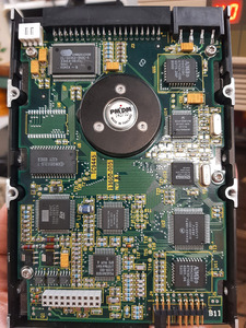
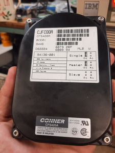
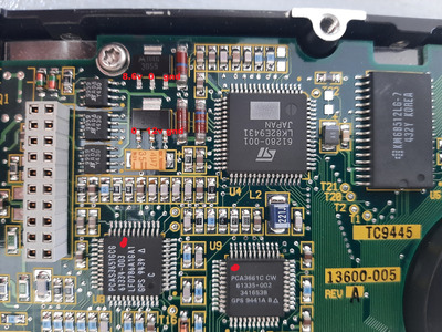
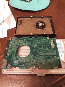
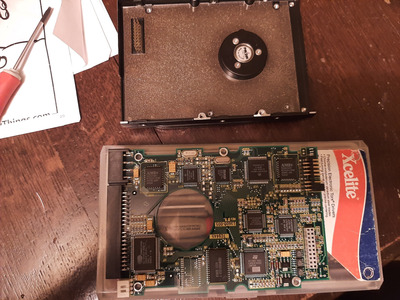
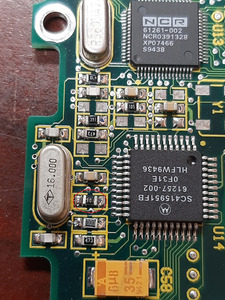
Have a conner 420MB ide that worked perfect, had used it several times in the past with zero issues. Pulled it out of my parts tote today to install in my 386 build i am revamping and the drive is dead as in absolutely no motor sounds, no ticking, nothing just dead. I confirmed that 5v is present on various parts of the pcb. Nothing gets hot on the pcb anywhere. I tried two different power supplies too, but can confirm the molex connection on pcb does show 12v. Any ideas on what I should focus on?

Attachments

Reply 2 of 14, by TheMobRules

User metadata
Rank Oldbie
Rank
Oldbie

I would check the tantalums on the board, see if any one of them is shorted (the ones between +5V/+12V and GND are probably OK, otherwise the power supply would fail to start, so focus on the others). Also check diodes, I've had one short on an HDD not long ago.

If it's not an electrical problem, then maybe one of the heads got stuck to the landing zone on the platter, in this case you can try to (gently but firmly) shake the drive to see if you can get it unstuck. In any case, try to discard any of these issues before opening the drive as that almost always ends badly, which would be sad if the drive is still OK mechanically.

Reply 3 of 14, by momaka

User metadata
Rank Member
Rank
Member

In addition to what TheMobRules said, I would also recommend to take off the PCB from the drive and re-seat it, along with any jumpers on the pins. Generally, poor/bad contacts on these old PCBs are not common, since they use pretty good quality materials and leaded solder. However, it's worth a try anyways.

Reply 4 of 14, by lowlytech

User metadata
Rank Member
Rank
Member

Had a few minutes to poke around on the drive. Took PCB off and reseated it. Didn't change anything unfortunately.

I took some voltage measurements around a transistor and it may give a better clue. There are two of them by the resistors? the top one shows 8.6v on left pin for about 10-15 seconds after power is applied, then it goes to zero voltage. Maybe the motor is trying to start but can't so it gives up? The bottom transistor that is identical shows a constant 12v on the middle pin, but 0 on the left pin. Looks like the right most pin is tied to ground. I tried to find a datasheet, but couldn't really nail down an exact match. Looks like a motorola part R46 3055. Also I didn't give it enough time before, but once the drive has power applied the two IC's marked with a red dot do heat up nice and toasty, but it is gradual. Maybe like 45 seconds to a minute before they get too hot to touch.

So far all tantalums seem to be not shorted or test okay unless I missed one.

20240429_145332.jpg
Filename
20240429_145332.jpg
File size
1.98 MiB
Views
535 views
File license
Public domain

Reply 5 of 14, by momaka

User metadata
Rank Member
Rank
Member

The fact that those transistors stop showing a voltage after a while also makes me think you might have a stuck head, preventing the spindle motor from spinning up... though why the motor is not making any buzzing or chirping noise is also a little suspicious (generally, this is what HDDs do when the spindle motor is seized.) Give the hard drive a hard tap on the side(s) - i.e. parallel to the platter surface, to hopefully knock the heads loose. Do this as soon as you power up the drive. I have a Maxtor that does this every once in a while, and the solution has always been to hit it on the side every time.

If that doesn't seem to work, then let's do some tracing.
Take the PCB off again and see if you can find the contacts for the spindle motor. I'm not too familiar with old drives like this, but I presume they used 3-phase motors even back then like modern drives do? Whatever the case, see if the contacts for the motor lead to those two transistors you pointed to in the above picture. Maybe that can give us another clue.

Reply 7 of 14, by DAVE86

User metadata
Rank Newbie
Rank
Newbie

The 61280-001 controller has supervisor functions. If the pulsed current is maximum but the spindle is unable to spin up it cuts the power. Could it be that the issue is not electrical? These old Conner drives use a rubber gasket between the drive assembly base and top cover that sometimes deteriorate and turn into an oily mush. This fluid can seep into the insides, deposit on the surfaces and heads making it stuck.

Reply 8 of 14, by Deunan

User metadata
Rank Oldbie
Rank
Oldbie
lowlytech wrote on 2024-04-29, 00:31:

the drive is dead as in absolutely no motor sounds, no ticking, nothing just dead

Stuck heads would be my guess. Find a medium size screwdriver with a wooden or ruberized handle. Tap the HDD a few times on the side while powering up (note, some HDDs give up trying to spin so it's best to cut the power and retry). Try it in different positions, esp. on the side and on the back as sometimes the gravity can also help. DO NOT tap the drive from top or bottom, that is at sides with large surface area. This will only impact the heads into the platters and cause more damage.

If nothing helps you can open it and try to spin the platters with your finger but chances are this will damage the head suspension or even rip them off anyway. But at that point it's dead one way or another so...

Reply 9 of 14, by lowlytech

User metadata
Rank Member
Rank
Member

Well I took my Klein rubber handled screwdriver and gave it a few good hits on the side, doesn't make a peep. I am familiar with stuck heads as I have bumped drives in the past that got stuck say over the humid summer without A/C, in a lab at a school, but those would at least make a low buzz or some motor sound. The silly drive worked like a month ago, and was stored in my climate controlled office inside a static bag. I was floored when it was just dead.

In the past I had a miniscribe drive I believe that was completely gunked from the rubbery ooze, been there done that, but I want to say I still could hear the motor binding or buzzing when that drive fell to that fate. I just hate opening the drive up unless everything else fails.

Took the PCB back off and the pins go inside the drive I guess, I can't tell which ones go to the motor.

On the tantalums that you say power has to be going through to have a failure. If I power up the drive what do I need to do to test these tantalums?

20240503_215945.jpg
Filename
20240503_215945.jpg
File size
1.57 MiB
Views
277 views
File license
Public domain
20240503_215910.jpg
Filename
20240503_215910.jpg
File size
1.67 MiB
Views
277 views
File license
Public domain

Reply 10 of 14, by Deunan

User metadata
Rank Oldbie
Rank
Oldbie
lowlytech wrote on 2024-05-04, 03:16:

Took the PCB back off and the pins go inside the drive I guess, I can't tell which ones go to the motor.

On this drive the main spindle motor is powered through the same connector as the head amp and coil. It's unlikely it failed so badly the HDD won't spin, these connectors are pretty robust and it takes a lot of clearly visible corrosion to take them out. Anything else fixes itself just by removing and reinstalling the PCB (any oxidation gets scraped off).

lowlytech wrote on 2024-05-04, 03:16:

On the tantalums that you say power has to be going through to have a failure. If I power up the drive what do I need to do to test these tantalums?

Since these are all on the other side of the PCB I don't think there is any way to test them with power applied unless the PCB is out of the drive, or wires are soldered. But with the PCB out it can be done - all you need is a volt meter, make sure there is some voltage present on each capacitor. Usually these filter power supply so there will be 12V or 5V, or maybe something like 3V3 if there is a voltage regulator nearby. A shorted cap will have next to zero voltage on it (but typically the copper offers so little resistance that such a short results in combustion, so if any caps went bad it would not be the ones close to power connector).

Do be super careful to not short something with the meter probe tip. There is often little room for the tip and if you short (even very briefly) 12V to some logic signals it's bye-bye drive electronics. For that reason it's usually much safer to just check the unpowered PCB for any obvious shorts. If there are no low readings (a couple of ohms or less) there is no point in risking powered testing. I've yet to see a shorted tantalum cap that would only short with power applied but show OK-ish during resistance measurement.

Reply 11 of 14, by momaka

User metadata
Rank Member
Rank
Member

Just a thought that occurred to me: perhaps one of the two crystals on the board went bad, thus preventing the IC(s) from getting a clock signal?
I've had this happen on the controller of my nephew's toy RC car.
Usually it takes either thermal or physical shock, though... which of course doesn't seem too likely if the drive was nicely stored. But nevertheless, worth keeping in mind, especially if you have some scrap boards / electronics that have crystals with this exact clock frequency and could attempt a swap.

But before diving in and doing anything with the crystals, I suggest checking all of the small ceramic caps for short-circuit. Any that might be used for signal coupling could be a probable cause for this issue if they are short-circuited (which is their typical failure mode.)
Last but not least, give all of the small SMD resistors a quick test too. The high-value ones (300+ KOhms) are often susceptible to going open-circuit. I've fixed numerous devices due to this exact fault. At least this drive is old enough that most/all of the resistors have their value labeled on top, so you can kind of get an idea what they should measure. Note that in-circuit resistance measurements can be a bit tricky. Usually, it's OK if a resistor measures much lower in value than what its rated value is. On the other hand, if the resistor measures much higher value than its rated, then it could very likely be bad.

Reply 12 of 14, by lowlytech

User metadata
Rank Member
Rank
Member
momaka wrote on 2024-05-06, 19:41:
Just a thought that occurred to me: perhaps one of the two crystals on the board went bad, thus preventing the IC(s) from gettin […]
Show full quote

Just a thought that occurred to me: perhaps one of the two crystals on the board went bad, thus preventing the IC(s) from getting a clock signal?
I've had this happen on the controller of my nephew's toy RC car.
Usually it takes either thermal or physical shock, though... which of course doesn't seem too likely if the drive was nicely stored. But nevertheless, worth keeping in mind, especially if you have some scrap boards / electronics that have crystals with this exact clock frequency and could attempt a swap.

But before diving in and doing anything with the crystals, I suggest checking all of the small ceramic caps for short-circuit. Any that might be used for signal coupling could be a probable cause for this issue if they are short-circuited (which is their typical failure mode.)
Last but not least, give all of the small SMD resistors a quick test too. The high-value ones (300+ KOhms) are often susceptible to going open-circuit. I've fixed numerous devices due to this exact fault. At least this drive is old enough that most/all of the resistors have their value labeled on top, so you can kind of get an idea what they should measure. Note that in-circuit resistance measurements can be a bit tricky. Usually, it's OK if a resistor measures much lower in value than what its rated value is. On the other hand, if the resistor measures much higher value than its rated, then it could very likely be bad.

Good idea on the crystals. I will try and find where the clock signals go to the chips and see if they are present. Had a bit of time to probe some of the passives and the only thing that seems strange to me so far is one resistor with a "106" on the top reading at 0.724 Megaohms This is right beside the 16.000 crystal too

20240509_102904.jpg
Filename
20240509_102904.jpg
File size
1.08 MiB
Views
145 views
File license
Public domain

Reply 14 of 14, by Deunan

User metadata
Rank Oldbie
Rank
Oldbie

Note that some of these clocks can be gated. I have a dead drive that has 3 crystals and one clock is missing, but it's because the generator circuit is disabled by the on-board MCU. There is no clock to the spindle motor controller but the MCU runs, it's just unhappy about something (or its internal ROM is glitched). I even replaced the external SRAM chip (this move revived another dead HDD that now works) but still no-go. So sometimes the problem can be rather difficult to diagnose and swapping the PCBs is not always an option - you need to have one on hand, and it has to be of the same revision or else it won't work properly.