VOGONS


First post, by Skyscraper

User metadata
Rank l33t
Rank
l33t

As we all know slotkets for PPGA dosnt work with Coppermine CPUs without modification.
I have a MSI 6905 v1.1 that would only work with old PPGA Celerons. Coppermine CPUs would not even post.

Here is a link that describes the mod.

http://krick.3feetunder.com/370mod/

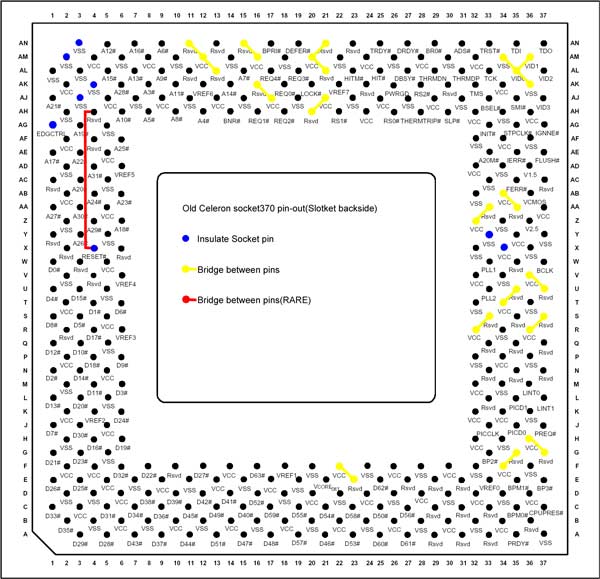
I removed the pin AM2.

The other half of the mod is done by soldering a cable between two reset pins.
I thought that I might aswell try the slotket to see if it would work without the two reset pins connected.
To my surprise it worked.

The pins that you are supposed to connect are AH4 "RESET (AGTL + INPUT)" and X4 "RESET2 (AGTL + I/O)" only the latter is used on PPGA as "RESET (AGTL + INPUT)"
So only RESET2 will get a signal at the moment.

Why does it work ? 😀
Isnt the first RESET signal needed?

Perhaps someone with more knowledge could explain whats those reset signals are used for?

I cant seem to find the manual for the slotket MS6905 v1.1.
I have found the manual for the Coppermine ready"MS6905 Master" slotket.
There are two unmarked jumpers present on my slotket and I want to know what they do.
The voltage selection block is simular to the MS6905 Master only with less options.

EDIT

It seems it only works with a 66 mhz fsb CPU
The Celeron 566 I tried first because its an expendable CPU worked perfectly.
It even overclocked to 8.5*112 = 952 @ 1.85v and there were no stability issues that I noticed.
Celeron 850 would not post.
P3 850 would not post.
P3 1000(133) would not post.
Im not sure if this is because of the half finished mod.

/EDIT

New PC: i9 12900K @5GHz all cores @1.2v. MSI PRO Z690-A. 32GB DDR4 3600 CL14. 3070Ti.
Old PC: Dual Xeon X5690@4.6GHz, EVGA SR-2, 48GB DDR3R@2000MHz, Intel X25-M. GTX 980ti.
Older PC: K6-3+ 400@600MHz, PC-Chips M577, 256MB SDRAM, AWE64, Voodoo Banshee.

Reply 1 of 53, by Skyscraper

User metadata
Rank l33t
Rank
l33t

I tried an Asus PPGA slotket also with removed AM2 pin.
The result is the same. The Celeron 566 works great but not 100 mhz FSB CPUs or 133 mhz FSB CPUs
With the Asus slotket my motherboards fail to detect the voltage I set with jumpers on the slotket but it detects the Celerons default voltage correctly.
With the MSI slotket the jumper selection block on the slotket works.

I will solder cables to bridge the reset signal pins as soon as I have bought a better tip for my soldering station.
I hope that will solve the issues but for some reason I doubt it.

New PC: i9 12900K @5GHz all cores @1.2v. MSI PRO Z690-A. 32GB DDR4 3600 CL14. 3070Ti.
Old PC: Dual Xeon X5690@4.6GHz, EVGA SR-2, 48GB DDR3R@2000MHz, Intel X25-M. GTX 980ti.
Older PC: K6-3+ 400@600MHz, PC-Chips M577, 256MB SDRAM, AWE64, Voodoo Banshee.

Reply 2 of 53, by TELVM

User metadata
Rank Oldbie
Rank
Oldbie

I think PPGA 66MHz Celerons expect RESET# on pin X4 (that why your 66MHz Celeron 566 works OK without bridging X4 to AH4), while FC-PGA 100MHz Celerons/Coppermines expect RESET# on pin AH4 (that's why every 100MHz CPU you try doesn't post without bridging X4 to AH4).

Here's the hardcore pr0n: http://www.intel.com/design/celeron/datashts/24365820.pdf

Let the air flow!

Reply 3 of 53, by Skyscraper

User metadata
Rank l33t
Rank
l33t

Yes but this 566 mhz Celeron is a Coppermine FC-PGA Celeron not a PPGA one.
The fastest PPGA Celeron is 533 mhz.
The PPGA package does not resemble the FC-PGA flip chip package with naked core at all.
I have a Celeron 500 PPGA in one of my retro systems. I am not totally clueless 😁

But I guess this 566mhz 66 mhz FSB FC-PGA Celeron perhaps works as the PPGA ones when it comes to that reset signal.
Thanks for the link!

New PC: i9 12900K @5GHz all cores @1.2v. MSI PRO Z690-A. 32GB DDR4 3600 CL14. 3070Ti.
Old PC: Dual Xeon X5690@4.6GHz, EVGA SR-2, 48GB DDR3R@2000MHz, Intel X25-M. GTX 980ti.
Older PC: K6-3+ 400@600MHz, PC-Chips M577, 256MB SDRAM, AWE64, Voodoo Banshee.

Reply 4 of 53, by TELVM

User metadata
Rank Oldbie
Rank
Oldbie

Forget the PPGA part, what I mean is that it seems 100 MHz CPUs need RESET# on AH4 to initialize properly.

Make sure that the 'Reset#'-signal of Socket370, that arrives at the useless 'Reset2#'-pin (X4) of Coppermine gets 'redirected' to Coppermine's 'Reset#'-pin (AH4).

http://www.tomshardware.com/reviews/fc,167-6.html

Let the air flow!

Reply 5 of 53, by Skyscraper

User metadata
Rank l33t
Rank
l33t

😀

That Toms hardware link is great.
His picture shows the exakt same two pins as the link I posted.
I really like when diffrent sources agree on this stuff.
It looks like the page I linked to even used the picture from Toms hardware to show the finished job 😁

I really need to get a new narrow tip for my soldering station.
Things are stacking up.

New PC: i9 12900K @5GHz all cores @1.2v. MSI PRO Z690-A. 32GB DDR4 3600 CL14. 3070Ti.
Old PC: Dual Xeon X5690@4.6GHz, EVGA SR-2, 48GB DDR3R@2000MHz, Intel X25-M. GTX 980ti.
Older PC: K6-3+ 400@600MHz, PC-Chips M577, 256MB SDRAM, AWE64, Voodoo Banshee.

Reply 6 of 53, by TELVM

User metadata
Rank Oldbie
Rank
Oldbie
"As you may already be aware, the RESET# pin moved when the Pentium3 was designed and RESET2# was added to the Tualatin design. […]
Show full quote

"As you may already be aware, the RESET# pin moved when the Pentium3 was designed and RESET2# was added to the Tualatin design. RESET2#, pin AJ3, was added by Intel to prevent Tualatin CPUs from operating with non-i815E stepping B chipsets so we will merely insulate and forget about it. But we must bridge the old location of RESET#, pin X4, to the new Pentium3/Tualatin RESET# pin as depicted in Diagram 1 with a Red line."

oldceleronpin.jpg

http://www.oocities.org/_lunchbox/tualeron_zm6_mod.html

Let the air flow!

Reply 7 of 53, by Skyscraper

User metadata
Rank l33t
Rank
l33t
TELVM wrote:

"As you may already be aware, the RESET# pin moved when the Pentium3 was designed and RESET2# was added to the Tualatin design. RESET2#, pin AJ3, was added by Intel to prevent Tualatin CPUs from operating with non-i815E stepping B chipsets so we will merely insulate and forget about it. But we must bridge the old location of RESET#, pin X4, to the new Pentium3/Tualatin RESET# pin as depicted in Diagram 1 with a Red line."

http://www.oocities.org/_lunchbox/tualeron_zm6_mod.html

I am waiting for a Tualatin Celeron 1400.
I bought it on Ebay a few days ago so it will be here ...in 2 - 4 weeks 😁
I took one quick look at the mod for making a normal FC-PGA sloket work with a Tualatin and decided to not even try.
The CPU I ordered is modded so it will fit in a normal FC-PGA slotket.
One of the reasons for me tinkering with the PPGA slotkets is that I do not have a working FC-PGA slotket with voltage selection.

I will buy a P3 1400 aswell from the same seller but I cant order both CPUs at the same time.
Only small packages with little value slip through the net.

New PC: i9 12900K @5GHz all cores @1.2v. MSI PRO Z690-A. 32GB DDR4 3600 CL14. 3070Ti.
Old PC: Dual Xeon X5690@4.6GHz, EVGA SR-2, 48GB DDR3R@2000MHz, Intel X25-M. GTX 980ti.
Older PC: K6-3+ 400@600MHz, PC-Chips M577, 256MB SDRAM, AWE64, Voodoo Banshee.

Reply 8 of 53, by gerwin

User metadata
Rank l33t
Rank
l33t

I don't have the time to read into this topic and my own notes,
But a past conlusion of mine was to stop bothering with slotkets lacking a voltage clamp chip. I found they work in some setups and malfunction in others. They do not properly convert the signals:

source "Actually the CMOS signal groups are specified as 2.5v on Slot 1 processors and 1.5v on S370 processors. These signals are routed through the TVC16222A precisely to protect the CPU from 2.5v on 1.5v pins."

--> ISA Soundcard Overview // Doom MBF 2.04 // SetMul

Reply 9 of 53, by Skyscraper

User metadata
Rank l33t
Rank
l33t

The Celeron 566 will be a guinea pig.

With the MSI-slotket I have noticed following
If I set the jumper block to auto voltage I get 1.5V from the motherboard and with luck the CPU gets 1.5V
If I set the voltage block to 1.8V I still get 1.5V until I do a bios reset wih the jumper. After that I get 1.8V from the motherboard and maybe the CPU gets 1.8V
If I set 2V in the bios setup while having the jumper block set to 1.8V I get 1.8V from the motherboard and perhaps the CPU still gets 1.8V...
The jumper block seems to pick the voltage it wants from the VRM directly and the bios setup can not override it...
...Except if the slotket is jumpered to use auto voltage or if the BIOS was not reset since last time you had the slotket jumpered to use auto voltage. Then voltage in bios setup work but max is 1.5V+0.2V.
Franz Kafka could not have designed it better.

New PC: i9 12900K @5GHz all cores @1.2v. MSI PRO Z690-A. 32GB DDR4 3600 CL14. 3070Ti.
Old PC: Dual Xeon X5690@4.6GHz, EVGA SR-2, 48GB DDR3R@2000MHz, Intel X25-M. GTX 980ti.
Older PC: K6-3+ 400@600MHz, PC-Chips M577, 256MB SDRAM, AWE64, Voodoo Banshee.

Reply 10 of 53, by gerwin

User metadata
Rank l33t
Rank
l33t

Some things are strange,
It should work like this:
-Normally CPU interfaces with Motherboard VRM chip directly to set the core voltage, through several VID pins, which are either 0 or 1.
-Slotket can be set to Auto, to keep it like this.
-Slotket can be set to Manual to ignore the CPU VID, and configure a different VID setting with jumpers.
-If the BIOS has core voltage adjusment it cannot allow direct VID connection between CPU/Slotket and VRM. But instead reads it from the CPU and sends a software modded setting to the VRM.

--> ISA Soundcard Overview // Doom MBF 2.04 // SetMul

Reply 11 of 53, by Skyscraper

User metadata
Rank l33t
Rank
l33t

That is how I thought it would work.

But in this case it seems the bios does not manage to modify the voltage selection signal if it comes from the jumper block and therefore it only sends it through to the VRM. The VRM reads the voltage selection correctly.
But if the voltage selection signal comes directly from the CPU (slotket set to auto voltage) the bios can modify the signal correctly and send a modified signal to the VRM.
But the strangest part is that the BIOS totally ignores the jumper blocks voltage selection until the bios is cleared with the jumper.
Removing the CPU and puting it back again does not make the voltage block come to life after auto voltage has ben used but switching to another CPU and changing back works...

Edit

Drunken ramblings

Could it be that the motherboard thinks those jumpers are actually the motherboards own jumpers and should therefore override the "jumper less" settings.
Then it would be normal to just pass the signal through. Motherboards with both jumpers and bios voltage selection do not let you tamper with both.
And the BIOS has no function to blank out the options the jumper block overrides becuase the motherboard is jumperless after all.
And there is no jumper to activate the jumperblock so the BIOS only reads the VID signal from it when the bios gets cleared.
I think when the BIOS reads the VID setting directly from the CPU it only does it once until the bios is cleared or the CPU is changed.
The rest of the time the BIOS remembers the VID and sends the signal to the VRM without reading it from the CPU.
But when the BIOS is cleared it notices the new VID and it also notices that it is set by jumpers because it is a VID the BIOS knows this CPU model do not use.
After that it reads the VID every reset to see if it changes. But it does not let you manipulate the voltage in the BIOS Setup.
Or it only reads the VID signal once but remembers that it was set with jumpers and still wont let you change the voltage in the BIOS setup until the bios is cleared or the CPU changed.
I will have to try to change the voltage from one non auto voltage setting to another using the voltage block to see if the BIOS picks it up without a clear.

/Drunken ramblings

/Edit

Last edited by Skyscraper on 2014-01-06, 01:47. Edited 3 times in total.

New PC: i9 12900K @5GHz all cores @1.2v. MSI PRO Z690-A. 32GB DDR4 3600 CL14. 3070Ti.
Old PC: Dual Xeon X5690@4.6GHz, EVGA SR-2, 48GB DDR3R@2000MHz, Intel X25-M. GTX 980ti.
Older PC: K6-3+ 400@600MHz, PC-Chips M577, 256MB SDRAM, AWE64, Voodoo Banshee.

Reply 12 of 53, by TELVM

User metadata
Rank Oldbie
Rank
Oldbie
gerwin wrote:

... a past conlusion of mine was to stop bothering with slotkets lacking a voltage clamp chip. I found they work in some setups and malfunction in others. They do not properly convert the signals:

source "Actually the CMOS signal groups are specified as 2.5v on Slot 1 processors and 1.5v on S370 processors. These signals are routed through the TVC16222A precisely to protect the CPU from 2.5v on 1.5v pins."

^ Wise words.

Clamp.jpg?noCache=1388971760

Let the air flow!

Reply 13 of 53, by Skyscraper

User metadata
Rank l33t
Rank
l33t
TELVM wrote:
^ Wise words. […]
Show full quote
gerwin wrote:

... a past conlusion of mine was to stop bothering with slotkets lacking a voltage clamp chip. I found they work in some setups and malfunction in others. They do not properly convert the signals:

source "Actually the CMOS signal groups are specified as 2.5v on Slot 1 processors and 1.5v on S370 processors. These signals are routed through the TVC16222A precisely to protect the CPU from 2.5v on 1.5v pins."

^ Wise words.

Clamp.jpg?noCache=1388971760

I have one FC-PGA slotket and 6 (edit make that 7) PPGA/PGA370 slotkets.

Not a single such chip between them.
The Guinea pig Celeron seem like a better and better idea.
3dmark2001 is still looping @ 952 mhz 😀
I do not dare to leave it on while I sleep.

New PC: i9 12900K @5GHz all cores @1.2v. MSI PRO Z690-A. 32GB DDR4 3600 CL14. 3070Ti.
Old PC: Dual Xeon X5690@4.6GHz, EVGA SR-2, 48GB DDR3R@2000MHz, Intel X25-M. GTX 980ti.
Older PC: K6-3+ 400@600MHz, PC-Chips M577, 256MB SDRAM, AWE64, Voodoo Banshee.

Reply 14 of 53, by Skyscraper

User metadata
Rank l33t
Rank
l33t

I tried soldering with the old not so narrow tip.
I feel that I need one more hand and a magnifying glass.
Perhaps it is time to get a pair of cheap reading glasses.

The result was bad and would probably shorted out the motherboard.
So I removed the cable again and resoldered the pins it was connected to.

Fixing the pins solder joints with out trying to attach the cable to them is not hard at all. It is when the third hand is needed I screw up.
To little solder , to much solder, cold joints, shorts you name it. I need to do these kind of mods more often so I get used to holding the cable that needs to be soldered and the solder in the same hand.
When soldering caps and such this isnt a problem since it is easy to fix the cap in place so you dont need 3 hands when soldering 😀

New PC: i9 12900K @5GHz all cores @1.2v. MSI PRO Z690-A. 32GB DDR4 3600 CL14. 3070Ti.
Old PC: Dual Xeon X5690@4.6GHz, EVGA SR-2, 48GB DDR3R@2000MHz, Intel X25-M. GTX 980ti.
Older PC: K6-3+ 400@600MHz, PC-Chips M577, 256MB SDRAM, AWE64, Voodoo Banshee.

Reply 16 of 53, by Skyscraper

User metadata
Rank l33t
Rank
l33t
TELVM wrote:

If you pre tin the wire tip, you can do without a third hand holding the solder: http://www.youtube.com/watch?v=DT5RUHAMshA

That seems to be a great idea!
Thanks!

New PC: i9 12900K @5GHz all cores @1.2v. MSI PRO Z690-A. 32GB DDR4 3600 CL14. 3070Ti.
Old PC: Dual Xeon X5690@4.6GHz, EVGA SR-2, 48GB DDR3R@2000MHz, Intel X25-M. GTX 980ti.
Older PC: K6-3+ 400@600MHz, PC-Chips M577, 256MB SDRAM, AWE64, Voodoo Banshee.

Reply 18 of 53, by Skyscraper

User metadata
Rank l33t
Rank
l33t
kokornov wrote:

Early FCPGA Celerons (533A/566, 1.5v) can work in PPGA boards/slotkets without modifications. Later models will fall into reset loop.

That explains it.
They sure were quick to fix that "bug".
Noooo it works... make it fail!

New PC: i9 12900K @5GHz all cores @1.2v. MSI PRO Z690-A. 32GB DDR4 3600 CL14. 3070Ti.
Old PC: Dual Xeon X5690@4.6GHz, EVGA SR-2, 48GB DDR3R@2000MHz, Intel X25-M. GTX 980ti.
Older PC: K6-3+ 400@600MHz, PC-Chips M577, 256MB SDRAM, AWE64, Voodoo Banshee.

Reply 19 of 53, by TELVM

User metadata
Rank Oldbie
Rank
Oldbie
Skyscraper wrote:

... They sure were quick to fix that "bug" ... ... Noooo it works... make it fail!

Exactly. All this playing with the pins was to ensure no forward compatibility and thus force the flock to 'upgrade' mobo. See here and here.

That's one of the reasons why making a Tually work on a 440BX was so gratifying 😎 . Eppur si muove! icon_twisted.gif

Let the air flow!