Reply 60 of 71, by snufkin
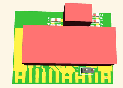
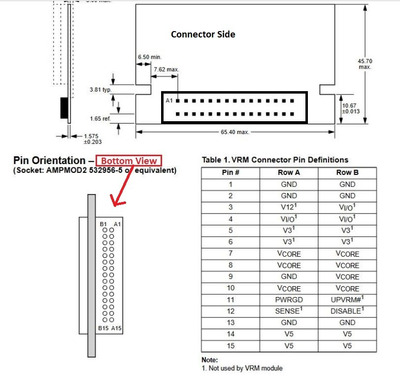
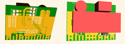
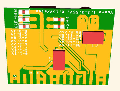
Bit of fiddling around and I think I've got a carrier PCB that fits with the pinout from that datasheet in my previous post. I've used that trick of putting the PCB between the pins of a connector (I think I've seen that before on a programmer header). I'm reasonably happy with the routeing, and there's space to add an 8mm diameter poly input cap at the top left, close to the input to the module. Because of where the Vout pin on the module is there's no where good to put an output capacitor without making the module 8mm taller, but I think it should be ok just using the output caps on the module itself. Something could be bodged in place if it turns out it's needed. It's approximately 40mm wide and 30mm tall, with all the components on the back. I don't know if it matters that the components are on the back, but that made the routeing a lot neater. It's got a right-angle 16 position rotary switch fitted, so that should be accessible from the top, and using the resistor values from the previous carrier should give 1.3V-3.55V in 0.15 steps. It's easy enough to work out different starting points and step sizes. if needed.
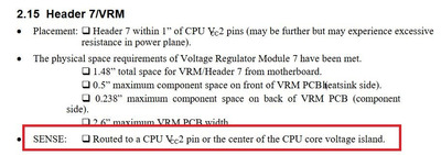
I've put a jumper in for the V3 to Vi/o connection, just in case there's a need to have a different voltage for io. I've routed the sense pin to the sense+ input on the module, and also the power good. I've routed the Disable signal to On/Off, but I need to check up on the polarity of the input to the module (from reading Intel AP579 is it high to turn off the VRM outputs).
What do you think? I'm going to add that input capacitor, check on the on/off polarity, then put in some text.