VOGONS


DigiPOS adventures!

Topic actions

Reply 40 of 56, by megatron-uk

User metadata
Rank Oldbie
Rank
Oldbie

Yes, the 5v supply on the PicoPSU is substantially lower than the 12v supply. I guess I'm pretty close to the limit.

My collection database and technical wiki:
https://www.target-earth.net

Reply 41 of 56, by megatron-uk

User metadata
Rank Oldbie
Rank
Oldbie

Yeah, the reboots were definitely power draw issues - plugged a Corsair 450w PSU into the breakout header and it completed all the benchmarks without issue (except Comptest; with the MMX processor that one locks up every time). I'll need to find an alternative power supply for this thing, as I am not intending to put the non-standard PSU back in with its horrid 40mm cooling fan.

I think the brownouts may have damaged by Startech CF bay adapter though - I don't get any cards detected in it, but using the same IDE cable, FDD power connector and CF card, but on a cheap no-brand IDE/CF adapter it all works again. The Startech reader does have a capacitor on it though - I guess it's possible that it's failed.

My collection database and technical wiki:
https://www.target-earth.net

Reply 43 of 56, by DerBaum

User metadata
Rank Oldbie
Rank
Oldbie
mattsbone wrote on 2023-10-02, 12:45:

Has anyone got the secondary IDE working on this Digipos? There is a 40 pin header on the riser card, but I can't get to work.

Are you sure it is an IDE connector?
If your system works like a normal single baord computer the backplane is more or less passive.
The ide controller should be on the main cpu card. on regular sbc systems the ide channel is not available on the bus of the backplane.
I have seen backplanes with integrated controllers so its possible that it is that way, but thats not common.

But that said im not sure if your SBC connector is EISA (or just something that looks like it) and what it shares on the bus...

FCKGW-RHQQ2

Reply 44 of 56, by mattsbone

User metadata
Rank Newbie
Rank
Newbie

Ah ok so maybe the secondary ide is not available, I just thought the 40 pin header on the riser was it.

Attachments

Reply 45 of 56, by megatron-uk

User metadata
Rank Oldbie
Rank
Oldbie

I never tried it - you would probably want to trace out the pins from that connector to see where they go on the main board. It could be anything really.

My collection database and technical wiki:
https://www.target-earth.net

Reply 46 of 56, by Thermalwrong

User metadata
Rank Oldbie
Rank
Oldbie

I've got the later K6-2 equipped DigiPoS and I can confirm that the 50pin connector on the riser is actually IDE: Help with 50 pin IDE
Works with a CD-ROM drive but is a bit picky about which drives it works with - be cautious though, check for 5v on all the pins and note down which pins are ground, see if they line up with regular IDE before plugging stuff in. It's probably regular IDE though.

Reply 49 of 56, by Thermalwrong

User metadata
Rank Oldbie
Rank
Oldbie

yeah actually I do 🤣. I would've been showing them off by now but the 2nd IDE connection is a tad unreliable on my one, waiting for some new 44-pin 2mm pitch cables.

DigiPOS-CDrom-mounts.jpg
Filename
DigiPOS-CDrom-mounts.jpg
File size
292.34 KiB
Views
596 views
File license
CC-BY-4.0

Here you go - it's like revision 50. Needs a really slim bezel to be able to slide the case over the drive.

Needs to be printed in this orientation with no supports required:

DigiPOS-CDrom-mounts-printorientation.jpg
Filename
DigiPOS-CDrom-mounts-printorientation.jpg
File size
392.01 KiB
Views
596 views
File license
CC-BY-4.0

Attachments

Reply 50 of 56, by Thermalwrong

User metadata
Rank Oldbie
Rank
Oldbie
mattsbone wrote on 2023-10-02, 20:34:

Thanks, but I think this riser card maybe different, I can only get traces from CN1 to CN2.

On my later one the IDE pins go into the riser - incidentally is yours also a slot-1 connector?
From the riser connector it then goes directly to the chipset, I don't think I ever actually traced a signal connection on my one, just guessed it was IDE and was pleasantly surprised to find it worked.

Reply 52 of 56, by fu-ji-tsu

User metadata
Rank Newbie
Rank
Newbie

I have the Winchip C6 200 Mhz version of this Digipos, if I can somehow sort out a few things here and there this will be my ultimate MS-DOS and Windows 3.1 machine.

Has anyone managed to change the CMOS battery? At risk of sounding extremely ignorant, I have no idea where it is in my machine. There's an AWARD component that looks like a Dallas chip but I'd have thought that would be the BIOS?

I'm also finding it extremely fickle when it comes to recognising small SSD's (using a Startech converter) and compact flash cards. I have a stack of 8GB SSD's and I'd like to create a number of different installations and switch them using a 3'5" floppy bay SSD dock. However I'll also have to figure something out as I don't have the original floppy/IDE HD caddy. At any case, this is a fun little project.

Reply 53 of 56, by Thermalwrong

User metadata
Rank Oldbie
Rank
Oldbie

Ah before I forget, here's a new version of the inner side CD-rom mount.
Now the CD-rom can be fitted or removed with just the screws on the outer bracket, the inner bracket now has a box to enclose the edge of the drive.
That should mean it's much less awkward to put together, since the drive can now be installed after the bracket is in place.

Attachments

Reply 54 of 56, by megatron-uk

User metadata
Rank Oldbie
Rank
Oldbie
fu-ji-tsu wrote on 2023-10-10, 16:51:

I have the Winchip C6 200 Mhz version of this Digipos, if I can somehow sort out a few things here and there this will be my ultimate MS-DOS and Windows 3.1 machine.

Has anyone managed to change the CMOS battery? At risk of sounding extremely ignorant, I have no idea where it is in my machine. There's an AWARD component that looks like a Dallas chip but I'd have thought that would be the BIOS?

I'm also finding it extremely fickle when it comes to recognising small SSD's (using a Startech converter) and compact flash cards. I have a stack of 8GB SSD's and I'd like to create a number of different installations and switch them using a 3'5" floppy bay SSD dock. However I'll also have to figure something out as I don't have the original floppy/IDE HD caddy. At any case, this is a fun little project.

Yes, the award stickered component is a Dallas rtc. Desolder, fit socket and a replacement, or hack it and add a coin cell. I did the latter and it is working fine.

I *was* using the same startech 3.5 CF bay adapter on mine... but last time I powered it on it didn't detect it. I did initially have some trouble getting the CF card detected... and I can't remember what I did at the time to resolve it.

A P200mmx was a massive performance increase compared to the Winchip it came with. Jumpering as Cyrix enables the split voltage support, btw.

My collection database and technical wiki:
https://www.target-earth.net

Reply 55 of 56, by fu-ji-tsu

User metadata
Rank Newbie
Rank
Newbie

Thanks for the answer. I actually have a Pentium 200 MMX lying around that I will use for this purpose.

I have found the whole IDE set-up very touch and go. If you don't need to access the CF often I have found that the best solution is to have one of those adapters that let you use two CF cards, with one as master (OS, etc.) and another one as slave.

Reply 56 of 56, by justin1985

User metadata
Rank Member
Rank
Member

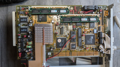
I've just given in to curiosity and bought one of the Celeron "DigiPOS Millennium" systems, from probably the same clothing retailer who has been selling the ones the rest of you have bought! From the photos, it looks like the board in this one is VIA based, with the ubiquitous 686B southbridge (so maybe with SB Pro emulation onboard?) . I liked the "Millennium" branding! Interestingly they also seem to have a breakout card slot header with audio and S-video out etc.

The Celeron based ones seem to have a 3 pin, rather than 4 pin, XLR power input, specified at 24v / 8A. The seller doesn't seem to be including or selling these with them, and is describing them as untested. Seeing as I don't have a 24V PSU of any kind, I'm tempted to skip straight to the PicoPSU stage. If it turns out to be totally dead, I figure I could even just use the outer chassis to conceal a ITX build instead ...

Has anyone else played around with the Celeron based ones?

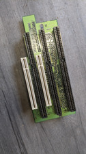
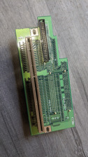
It seems like people did manage to track down the manuals for the Socket 7 equivalents - any tips that might help find the manual for this one? (Scratch that - I found the manual by including "Millennium" in the search term! http://support.epostraders.co.uk/support-file … hnicalGuide.pdf ) Are they some kind of relatively standard industrial NLX? The riser cards kind of look like NLX?