First post, by Tommaso74
Hi, it's my first post here but I'm a long-time reader of this valuable forum...
I'm in search of a bit of help, I hope a LCD tech guru can give me a hint.
Here's the problem:
I recently bought a COMPAQ Contura 3/25S whose screen suffered double-side vinegar syndrome. The screen showed the caracters (bios POST, DOS prompt etc.) only in the corners, the central part of the screen was unreadable.
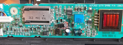
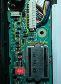
I disassembled the screen and noticed a leaked capacitor on the high voltage side of the PCB. The liquid has damaged the green plastic coating that protects some copper paths. I removed the bad cap, washed the area with isopropilic alcohol and soldered a good capacitor back in. Some copper paths are now naked, without coating. The copper paths aren't interrupted (the multimeter 'beeps'), but some paths are now almost black (oxydation?) under the coating film (see picture).

Now the bad part (oh well, the premises are bad too, but I mean, the really bad part)
When I turned on the notebook after the 'clean & recap' operation the screen began to act strange, intermittently showing the characters.
I tried to reseat the white ribbon that connects the motherboard to the screen PCB, but the characters disappeared definitely.
Any help? I have some soldering skills and a multimeter.
The backlight works well. The brightness sliding resistor works, it diminishes and increases the light bulb power perfectly.
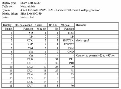
The 15 pins colored-wires connector from the PCB to the Sharp screen circuitry is ok (I tested every pin).
The white ribbon from the motherboard is also OK, no interrupted paths.
Pressing FN key + F3 (screen negative/positive) does nothing.
Pressing FN key + F4 (external/ internal screen) turns off and on an external monitor connected to the VGA port, as it should be, I can see everything (bios, prompt, programs etc.), and I can see colors, too.
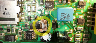
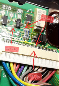
In the picture, the area surrounded by a yellow circle is a large copper path where the positive extremity of a SMD tantalum capacitor is soldered, it originally showed 0.02 volts but after cleaning that area with heated soldering paste it now measures 0.57 volts.
The screen contrast sliding resistor make it drop to 0.52 volts when set to the left side. This copper line ends to the 2 V-in pins of a LM337 integrated circuit. Is it normal that a so low voltage is given to this IC? Do you think that this LM337 IC controls only the screen contrast? Could it be that the contrast is so low that the screen doesn't show the characters, that are there, but remain 'invisible' because of low contrast?
Some voltages I found around in the PCB are steady: 4.9V, 18.1V, 1.2V.
Wow, long post... sorry!
Thank you in advance